![[ANSYS, Inc. Logo]](fluentlogo.gif)


|
|
|
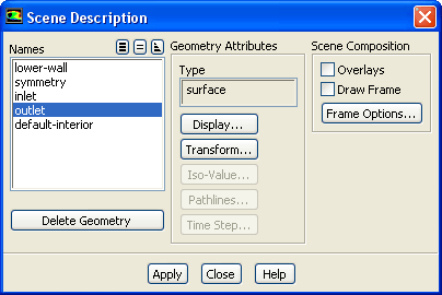
Once you have displayed some geometric objects (meshes, surfaces, contours, vectors, etc.) in your graphics window, you may want to move them around and change their characteristics to increase the effectiveness of the scene displayed. You can use the Scene Description dialog box (Figure 29.6.1) and the Display Properties dialog box (Figure 29.6.2) and Transformations dialog box (Figure 29.6.4), which are opened from within it, to rotate, translate, and scale each object individually, as well as change the color and visibility of each object.
 Graphics and Animations
 Scene...
The Iso-Value dialog box (Figure 29.6.5), which is also opened from within the Scene Description dialog box, allows you to change the isovalue of a selected isosurface. The Pathline Attributes dialog box (Figure 29.6.6) lets you set some pathline attributes. The ability to make geometric objects visible and invisible is especially useful when you are creating an animation (see Section 29.7) because it allows you to add or delete objects from the scene one at a time. The ability to change the color and position of an object independently of the others in the scene is also useful for setting up animations, as is the ability to change isosurface isovalues. You will find the features in the Scene Description dialog box useful even when you are not generating animations because they allow you to manage your graphics window efficiently. The procedure for overlaying graphics, which uses the Scene Description dialog box, is described in Section 29.2.1. (Note that you cannot use the Scene Description dialog box to control XY plot and histogram displays.)
Previous:
29.5.4 Mirroring and Periodic