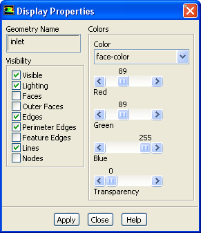
To modify the color, visibility, and other display properties for individual geometric objects in the graphics display, use the
Display Properties dialog box. You can open this dialog box by clicking the
Display... push button in the
Scene Description dialog box. See Section
29.6.2 for details about the items below.
Controls
Geometry Name
displays the name of the object you selected for modification in the
Scene Description dialog box.
Visibility
contains check buttons that control options related to the visibility of the selected object. See Section
29.6.2 for details.
Visible
toggles the visibility of the selected object. If it is turned on, the object will be visible in the display, and if it is turned off, the object will be invisible.
Lighting
turns the effect of lighting for the selected object on or off. You can choose to have lighting affect only certain objects instead of all of them. Note that if
Lighting is turned on for an object such as a contour or vector plot, the colors in the plot will not be exactly the same as those in the colormap at the left of the display.
Faces
toggles the filled display of faces for the selected mesh or surface object. Turning
Faces on has the same effect as turning on the display of faces in the
Mesh Display dialog box.
Outer Faces
toggles the display of outer faces.
Edges
toggles the display of interior and exterior edges of the geometric object.
Perimeter Edges
toggles the display of the outline of the geometric object. (This option has no effect on the display of meshes.)
Feature Edges
toggles the display of feature lines (if any) of the geometric object.
Lines
toggles the display of the lines (if any) in the geometric object.
Nodes
toggles the display of the nodes (if any) in the geometric object.
Colors
contains controls for setting face, edge, line, and node colors, and transparency for faces. See Section
29.6.2 for details.
Color
specifies the face, edge, line, or node color for modification. When you turn on this button, the color scales below will show the current color specification, which you can modify by moving the sliders on the color scales.
Red, Green, Blue
are color scales with which you can specify the RGB components of the face, edge or line color.
Transparency
sets the relative transparency of the selected object. An object with a transparency of 0 is opaque, and an object with a transparency of 100 is transparent.
![[ANSYS, Inc. Logo]](fluentlogo.gif)