![[ANSYS, Inc. Logo]](fluentlogo.gif)


|
|
|
When you are composing a scene in your graphics window, you might find it helpful to move a particular object from its original position or to increase or decrease its size. For example, if you have displayed contours or vectors on cross-sections of an internal flow domain (such as a pipe), you might want to translate these cross-sections so that they will appear outside of the pipe, where they can be seen and interpreted more easily. Figure 29.6.3 shows such an example.
You can also move an object by rotating it about the
 ,
,
 , or
, or
 axis. If you want to display one object more prominently than the others, you can scale its size. If your geometry is rotating or has rotational symmetry, you can display the meridional view. All of these capabilities are available in the
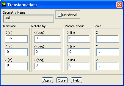
Transformations dialog box (Figure
29.6.4).
axis. If you want to display one object more prominently than the others, you can scale its size. If your geometry is rotating or has rotational symmetry, you can display the meridional view. All of these capabilities are available in the
Transformations dialog box (Figure
29.6.4).
To perform the transformations described above, select one or more objects in the Names list in the Scene Description dialog box and then click the Transform... button to open the Transformations dialog box for that object or group of objects.
Translating Objects
To translate the selected object(s), enter the translation distance in each direction in the X, Y, and Z real number fields under Translate. (Note that you can check the domain extents in the Scale Mesh dialog box or the Iso-Surface dialog box.) Translations are not cumulative, so you can easily return to a known state. To return to the original position, simply enter 0 in all three real number fields.
Rotating Objects
To rotate the selected object(s), enter the number of degrees by which to rotate
about each axis in the
X,
Y, and
Z integer number fields under
Rotate By. (You can enter any value between
 and
and
 .) By default, the rotation origin will be (0,0,0). If you want to spin an object about its own origin, or about some other point, specify the
X,
Y, and
Z coordinates of that point under
Rotate About.
.) By default, the rotation origin will be (0,0,0). If you want to spin an object about its own origin, or about some other point, specify the
X,
Y, and
Z coordinates of that point under
Rotate About.
Rotations are not cumulative, so you can easily return to a known state. To return to the original position, simply enter 0 in all three integer number fields under Rotate By.
Scaling Objects
To scale the selected object(s), enter the amount by which to scale in each direction in the X, Y, and Z real number fields under Scale. To avoid distortion of the object's shape, be sure to specify the same value for all three entries. Scaling is not cumulative, so you can easily return to a known state. To return the object to its original size, simply enter 1 in all three real number fields.
Displaying the Meridional View
To display the meridional view of the selected object(s), turn on the Meridional option. This option is available only for 3D models. It is applicable to cases with a defined axis of rotation and is especially useful in turbomachinery applications.
The meridional transformation projects the selected entities onto a surface of constant angular coordinate,
 . The resultant projection thus lies in an (
 ,
,
 ) plane where
 is in the direction of the rotation axis and
 is normal to it. The value of
 used for the projection is taken as that corresponding to the minimum (
 ,
,
 ) point of the entity.
Previous:
29.6.2 Changing an Object's