The
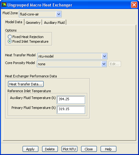
Ungrouped Macro Heat Exchanger dialog box allows you to set up the ungrouped macro heat exchanger model. See Section
14.3 for details about using this dialog box.
Controls
Fluid Zone
specifies the zone that represents the heat exchanger.
Model Data
contains the parameters related to the heat exchanger model.
Options
allows you to choose one of the following settings:
Fixed Heat Rejection
specifies that
ANSYS FLUENT should compute the auxiliary fluid inlet temperature for a specified heat rejection.
Fixed Inlet Temperature
specifies that
ANSYS FLUENT should compute the total heat rejection of the core for a given inlet auxiliary temperature.
Heat Transfer Model
allows you to specify either the
ntu-model or the
simple-effectiveness-model for heat transfer.
Core Porosity Model
contains a drop-down list of all available core porosity models.
Edit...
opens the
Core Porosity Model dialog box (see Section
14.3.6).
Heat Exchanger Performance Data
contains the parameters for heat transfer.
Heat Transfer Data...
opens the
Heat Transfer Data Table dialog box (see Section
3e). This item will appear for the NTU model only.
Auxiliary Fluid Temperature
specifies the auxiliary fluid temperature. This item will appear only for the NTU model.
Primary Fluid Temperature
specifies the gas stream temperature. This item will appear only for the NTU model.
Geometry
contains parameters to define the macro grid.
Width
sets the width of the heat exchanger core. The
Width is measured in the pass-to-pass direction.
Height
sets the height of the heat exchanger core. The
Height is measured in the auxiliary fluid inlet direction.
Depth
sets the depth of the heat exchanger core.
Number of Passes
specifies the number of passes for the macro grid. (See Figure
14.3.6.)
Number of Rows/Pass, Number of Columns/Pass
specify the number of macro rows and columns per pass in the macro grid. (See Figure
14.3.6.)
View Passes
displays the macro grid. (This button becomes available after you click
Apply.) The path of the auxiliary fluid is color-coded in the display: macro
is red and macro
is blue.
Draw Mesh
toggles between displaying and not displaying the mesh when the macro mesh is displayed (using the
View Passes button). The
Mesh Display dialog box opens when
Draw Mesh is selected.
Update from Plane Tool
updates the
Auxiliary Fluid Inlet Direction and
Pass-to-Pass Direction from the plane tool orientation. The
Width,
Height, and
Depth will also be updated. See Section
28.6.1 for information about using the plane tool.
Auxiliary Fluid Inlet Direction (height)
specifies the direction in which the auxiliary fluid enters the heat exchanger. See Figure
14.3.6.
Pass-to-Pass Direction (width)
specifies the direction in which the auxiliary fluid moves at the end of each pass through the heat exchanger. See Figure
14.3.6.
Auxiliary Fluid
contains the option to specify the auxiliary fluid properties.
constant-specific-heat
allows you to specific a constant value for the auxiliary fluid specific heat.
user-defined-enthalpy
allows you to specify a user-defined function for the auxiliary fluid enthalpy.
Auxiliary Fluid Specific Heat
specifies the value of
in
this equation in the separate
Theory Guide. This value is specified only if
constant-specific-heat is selected.
Auxiliary Fluid Enthalpy UDF
allows you to specify a UDF for the auxiliary fluid enthalpy (see
this equation in the separate
Theory Guide). This option is available only when
user-defined-enthalpy is selected.
Auxiliary Fluid Flow Rate
sets the flow rate of the auxiliary fluid (
in
this equation in the separate
Theory Guide).
Heat Rejection
sets the total heat rejection (
in
this equation in the separate
Theory Guide). This value is specified only if
Fixed Heat Rejection is selected.
Initial Temperature
sets an initial guess for the inlet temperature (
in
this equation and
this equation in the separate
Theory Guide). This value is specified only if
Fixed Heat Rejection is selected.
Inlet Temperature
sets the auxiliary fluid initial temperature (
in
this equation and
this equation in the separate
Theory Guide). This value is specified only if
Fixed Inlet Temperature is selected in the
Model Data tab.
Inlet Pressure
sets the auxiliary fluid inlet pressure. This value is specified only if
user-defined-enthalpy is selected.
Inlet Quality
specifies the value of
in
this equation in the separate
Theory Guide. This value is specified only if
user-defined-enthalpy is selected.
Pressure Drop
specifies the value of
in
this equation in the separate
Theory Guide. This value is specified only if
user-defined-enthalpy is selected.
Apply
saves all the settings for the heat exchanger specified in the
Fluid Zone list.
Delete
deletes the heat exchanger specified in the
Fluid Zone list.
![[ANSYS, Inc. Logo]](fluentlogo.gif)


 in
this equation in the separate
Theory Guide). This item will appear for simple effectiveness model only.
in
this equation in the separate
Theory Guide). This item will appear for simple effectiveness model only.
 is red and macro
 is blue.
 in
this equation in the separate
Theory Guide. This value is specified only if
constant-specific-heat is selected.
in
this equation in the separate
Theory Guide. This value is specified only if
constant-specific-heat is selected.
 in
this equation in the separate
Theory Guide).
in
this equation in the separate
Theory Guide).
 in
this equation in the separate
Theory Guide). This value is specified only if
Fixed Heat Rejection is selected.
in
this equation in the separate
Theory Guide). This value is specified only if
Fixed Heat Rejection is selected.
 in
this equation and
this equation in the separate
Theory Guide). This value is specified only if
Fixed Heat Rejection is selected.
in
this equation and
this equation in the separate
Theory Guide). This value is specified only if
Fixed Heat Rejection is selected.
 in
this equation and
this equation in the separate
Theory Guide). This value is specified only if
Fixed Inlet Temperature is selected in the
Model Data tab.
in
this equation and
this equation in the separate
Theory Guide). This value is specified only if
Fixed Inlet Temperature is selected in the
Model Data tab.
 in
this equation in the separate
Theory Guide. This value is specified only if
user-defined-enthalpy is selected.
in
this equation in the separate
Theory Guide. This value is specified only if
user-defined-enthalpy is selected.
 in
this equation in the separate
Theory Guide. This value is specified only if
user-defined-enthalpy is selected.
in
this equation in the separate
Theory Guide. This value is specified only if
user-defined-enthalpy is selected.