The heat exchanger model settings may be written into and read from the boundary conditions file (Section
4.7) using the text commands,
file/write-settings and
file/read-settings, respectively. Otherwise, the steps for setting up the ungrouped macro heat exchanger model is as follows:
- 1.
Enable the calculation of energy in the
Energy dialog box.
 Models

 Energy
 Edit...
- 2.
Enable the
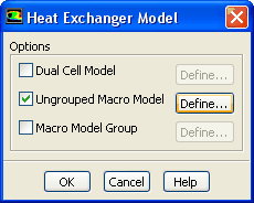
Ungrouped Macro Model option and click the
Define... button in the
Heat Exchanger Model dialog box
(Figure
14.3.1) to access the
Ungrouped Macro Heat Exchanger dialog box.
 Models

 Heat Exchanger
 Edit...
Figure 14.3.1: The
Heat Exchanger Model Dialog Box
 |
- 3.
Specify the heat exchanger inputs in the
Ungrouped Macro Heat Exchanger dialog box.
Figure 14.3.2: The
Ungrouped Macro Heat Exchanger Dialog Box Displaying the
Model Data Tab
 |
- (a)
In the
Fluid Zone drop-down list, select the fluid zone representing the heat exchanger core.
- (b)
Under the
Model Data tab, choose
Fixed Heat Rejection or
Fixed Inlet Temperature, as required (Figure
14.3.2).
- (c)
Specify the heat exchanger model as either the default
ntu-model or the
simple-effectiveness-model.
- (d)
Specify the
Core Porosity Model if you want
ANSYS FLUENT to use the pressure loss coefficient function to automatically compute (and update) the porous media coefficients in the cell zones condition dialog box, as described in
this section in the separate
Theory Guide. More information is available in Section
14.3.6.
- (e)
If the
ntu-model is chosen, a
Heat Transfer Data... button will appear under
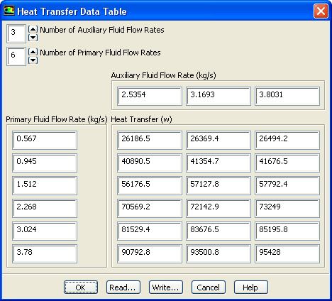
Heat Exchanger Performance Data. Clicking the
Heat Transfer Data... button will open up the
Heat Transfer Data Table dialog box
with information on the fluid flow rates and heat transfer data (Figure
14.3.3). More information is available in Section
14.3.2.
Figure 14.3.3: The
Heat Transfer Data Table Dialog Box for the NTU Model
 |
- (f)
Enter the
Auxiliary Fluid Temperature and the Primary Fluid Temperature for the
ntu-model. These are the fixed inlet temperatures at which the test was performed to obtain the heat transfer data.
- (g)
If the
simple-effectiveness-model is chosen, then clicking the
Velocity Effectiveness Curve... button, under the
Heat Exchanger Performance Data, allows you to set the velocity and corresponding effectiveness for each point. More information is available in Section
14.3.2.
- (h)
In the
Geometry tab, define the macro mesh using the
Number of Passes, the
Number of Rows/Pass, and the
Number of Columns/Pass fields. The
Number of Rows/Pass is along the auxiliary flow direction (height) and the
Number of Columns/Pass is defined in the pass-to-pass (width) direction. Also, enter the
Auxiliary Fluid Inlet Direction and
Pass-to-Pass Direction. You may want to snap the plane tool to either the inlet or outlet of the heat exchanger using the
Update from Plane Tool. Note that the plane tool must be attached exactly and oriented so that its green arrow points in the auxiliary flow direction, and its blue arrow points in the pass-to-pass direction.
|
-

|
To attach the plane tool exactly, exact coordinates (printed in the console by probing) of the three corner nodes must be entered in the plane tool (x0, x1, x2) in a specific order. Also, note that x0 to x1 is the auxiliary flow direction and x1 to x2 is the pass-to-pass direction.
|
More information is available in Sections
14.3.3 and
14.3.4.
Figure 14.3.4: The
Ungrouped Macro Heat Exchanger Dialog Box Displaying the
Geometry Tab
 |
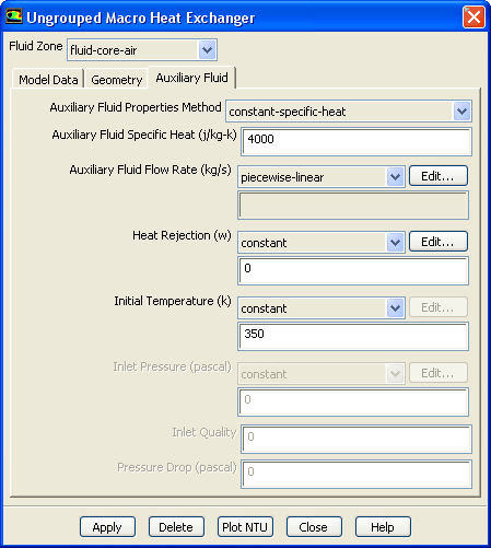
Figure 14.3.5: The
Ungrouped Macro Heat Exchanger Dialog Box Displaying the
Auxiliary Fluid Tab
 |
- (i)
In the
Auxiliary Fluid tab, specify the
Auxiliary Fluid Properties Method, either as a
constant-specific-heat or as a
user-defined-enthalpy.
- (j)
Auxiliary Fluid Flow Rate,
Heat Rejection,
Inlet Temperature, and
Inlet Pressure can be provided as a
constant,
polynomial or
piecewise-linear profile that is a function of time. If
user-defined-enthalpy is selected as the
Auxiliary Fluid Properties Method, you will need to specify the
Inlet Quality and the
Pressure Drop. More information is available in Section
14.3.5.
- (k)
Click
Apply in the
Ungrouped Macro Heat Exchanger dialog box to save all the settings. Once you click the
Apply button, the NTU matrix will be computed from the raw data. Therefore, make sure you click
Apply at the very end of your setup.
|
-

|
When you click
Apply, look for any error or warning message in the
ANSYS FLUENT console. Some of the common errors you may see displayed are due to the NTU computations not converging. In such cases, check that
- you have entered the data correctly
- the values of the data are reasonable
- the operating condition for the auxiliary fluid flow rate is not too far from the range of the heat transfer data
Other error messages you may encounter may be due to macros not getting any cells assigned to it. In such cases, make sure that
- the heat exchanger core is rectangular
- the directions are correct
- you are using uniformly spaced cells in both directions
- the mesh is either a hexahedra or wedge and is structured
|
- (l)
Repeat steps (a)-(k) for any other heat exchanger fluid zones.
To use multiple fluid zones to define a single heat exchanger, or to connect the auxiliary fluid flow path among multiple heat exchangers, see Section
14.4.


 Previous:
14.2.1 Restrictions
Previous:
14.2.1 Restrictions
Up:
14. Modeling Heat Exchangers
Next:
14.3.1 Selecting the Zone
Release 12.0 © ANSYS, Inc. 2009-01-29 ![[ANSYS, Inc. Logo]](fluentlogo.gif)

