![[ANSYS, Inc. Logo]](fluentlogo.gif)


|
|
|
As discussed in Section
14.1, the fluid zone representing the heat exchanger core is split into macros. Macros are constructed based on the specified number of passes, the number of macro rows per pass, the number of macro columns per pass, and the corresponding auxiliary fluid inlet and pass-to-pass directions (see Figure
14.3.6). Macros are numbered from
 to (
to (
 ) in the direction of auxiliary fluid flow, where
 is the number of macros.
In the Ungrouped Macro Heat Exchanger dialog box, in the Geometry tab, specify the Number of Passes, the Number of Rows/Pass, and the Number of Columns/Pass. The model will automatically extrude the macros to the depth of the heat exchanger core. For each pass, the Number of Rows/Pass are defined in the direction of the auxiliary flow inlet direction and the Number of Columns/Pass are defined in the direction of the pass-to-pass direction.
|
|
The
Number of Rows/Pass, as well as the
Number of Columns/Pass must be divisible by the number of cells in their respective directions. For example, if you have 50 cells in the auxiliary flow direction, you can use 25 for the
Number of Rows/Pass, but you should not use 26 or 24. If you have 51 cells in that direction, you can only use 51 for the
Number of Rows/Pass. The same holds true for the other direction.
|
Viewing the Macros
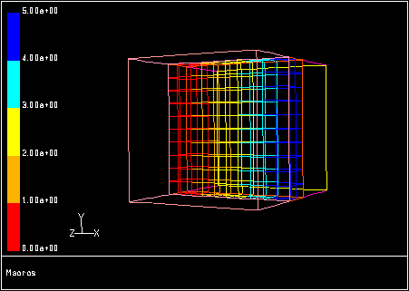
You can view the auxiliary fluid path by displaying the macros. To view the macros for your specified
Number of Passes,
Number of Rows/Pass, and
Number of Columns/Pass, click the
Apply button at the bottom of the dialog box, then click the
View Passes button to display it. The path of the auxiliary fluid is color-coded in the display: macro
 is red and macro
 is blue.
For some problems, especially complex geometries, you may want to include portions of the computational-domain mesh in your macros plot as spatial reference points. For example, you may want to show the location of an inlet and an outlet along with the macros. This is accomplished by enabling the Draw Mesh option. The Mesh Display dialog box will appear automatically when you enable the Draw Mesh option, where you can set the mesh display parameters. When you click the View Passes button in the Ungrouped Macro Heat Exchanger dialog box, the mesh display, as defined in the Mesh Display dialog box, will be included in the macros plot (see Figure 14.3.7).
Previous:
14.3.3 Specifying the Auxiliary
 3 Macros