To define a single heat exchanger that uses multiple fluid zones, or to connect the auxiliary fluid flow path among multiple heat exchangers, you can use heat exchanger groups. To use heat exchanger groups, perform the following steps:
- 1.
Enable the calculation of energy in the
Energy dialog box.
 Models

 Energy
 Edit...
- 2.
Enable the
Macro Model Group option and click the
Define... button in the
Heat Exchanger Model dialog box
to access the
Macro Heat Exchanger Group dialog box.
 Models

 Heat Exchanger
 Edit...
- 3.
Specify the inputs to the heat exchanger group in the
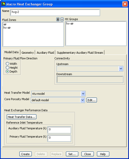
Macro Heat Exchanger Group dialog box (Figure
14.4.1).
Figure 14.4.1: The
Macro Heat Exchanger Group Dialog Box
 |
- (a)
Enter the
Name of the heat exchanger group.
- (b)
Under
Fluid Zones, select the fluid zones that you want to define in the heat exchanger group (Section
14.4.1).
- (c)
Click the
Model Data tab.
- i.
Under
Primary Fluid Flow Direction, specify the primary fluid flow direction as either
Width,
Height, or
Depth.
- ii.
Under
Connectivity, select the
Upstream heat exchanger group if such a connection exists (see Section
14.4.2).
- iii.
In the
Heat Transfer Model drop-down list, choose either the
ntu-model or the
simple-effectiveness-model (see Section
14.3.2).
- iv.
From the
Core Porosity Model drop-down list, specify the core model that should be used to calculate the porous media parameters for the zones in the group. More information is available in Section
14.3.6.
- v.
Provide the
Heat Exchanger Performance Data according to the chosen model.
- (d)
Click the
Geometry tab (Figure
14.4.2).
Figure 14.4.2: The
Macro Heat Exchanger Group Dialog Box -
Geometry Tab
 |
- i.
Define the macro mesh by specifying the
Number of Passes, the
Number of Rows/Pass, and the
Number of Columns/Pass. More information is available in Sections
14.3.3 and
14.3.4.
- ii.
Specify the
Auxiliary Fluid Inlet Direction and
Pass-to-Pass Direction (see Section
14.4.3).
- (e)
Click the
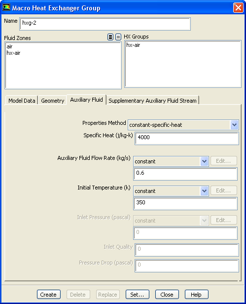
Auxiliary Fluid tab (Figure
14.4.3) to specify the auxiliary fluid operating conditions.
Figure 14.4.3: The
Macro Heat Exchanger Group Dialog Box -
Auxiliary Fluid Tab
 |
- i.
Specify the
Specific Heat as either a
constant-specific-heat or as a
user-defined-enthalpy.
- ii.
Auxiliary Fluid Flow Rate,
Initial Temperature, and
Inlet Pressure can be provided as a
constant,
polynomial or
piecewise-linear profile that is a function of time (see Section
14.3.5).
- (f)
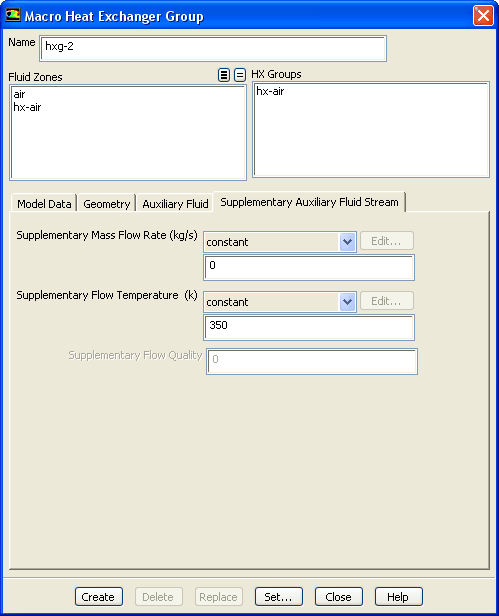
If a supplementary auxiliary stream is to be modeled, click the
Supplementary Auxiliary Fluid Stream tab.
Figure 14.4.4: The
Macro Heat Exchanger Group Dialog Box -
Supplementary Auxiliary Fluid Stream Tab
 |
- i.
You can specify the
Supplementary Mass Flow Rate as a
constant,
polynomial or
piecewise-linear profile that is a function of time.
- ii.
You can specify the
Supplementary Flow Temperature as a
constant,
polynomial or
piecewise-linear profile that is a function of time.
- (g)
Click
Create or
Replace in the
Macro Heat Exchanger Group dialog box to save all the settings.
Replace changes the parameters of the already existing group that is selected in the
HX Groups list.
|
-

|
Creating or replacing any heat exchanger group initializes any previously calculated values for temperature and enthalpy for all macros.
|
- 4.
If a heat exchanger group comprises multiple fluid zones and you wish to override any of the inputs defined in the previous steps, click the
Set... button to open the
Ungrouped Macro Heat Exchanger dialog box (Figure
14.3.2). Select the particular fluid zone as usual. Notice that the individual heat exchanger inherits the properties of the group by default. You may override any of the following:
-
Number of Passes,
Number of Rows/Pass, and
Number of Columns/Pass
-
Auxiliary Fluid Inlet Direction and the
Pass-to-Pass Direction
-
Core Porosity Model


 Previous:
14.3.6 Setting the Pressure-Drop
Previous:
14.3.6 Setting the Pressure-Drop
Up:
14. Modeling Heat Exchangers
Next:
14.4.1 Selecting the Fluid
Release 12.0 © ANSYS, Inc. 2009-01-29 ![[ANSYS, Inc. Logo]](fluentlogo.gif)

