[ANSYS, Inc. Logo] return to home search
next up previous contents index

23.3.15 Defining Injection Properties

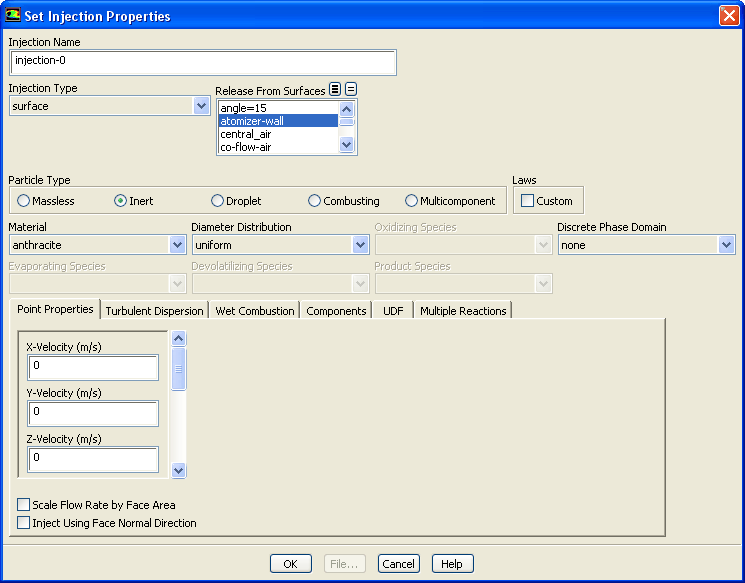
Once you have created an injection (using the Injections dialog box, as described in Section  23.3.14), you will use the Set Injection Properties dialog box (Figure  23.3.9) to define the injection properties. (Remember that this dialog box will open when you create a new injection, or when you select an existing injection and click the Set... button in the Injections dialog box.)

Figure 23.3.9: The Set Injection Properties Dialog Box
figure

The procedure for defining an injection is as follows:

1.   If you want to change the name of the injection from its default name, enter a new one in the Injection Name field. This is recommended if you are defining a large number of injections so you can easily distinguish them. When assigning names to your injections, keep in mind the selection shortcut described in Section  23.3.14.

2.   Choose the type of injection in the Injection Type drop-down list. The eleven choices ( single, group, cone, solid-cone, surface, plain-orifice-atomizer, pressure-swirl-atomizer, air-blast-atomizer, flat-fan-atomizer, effervescent-atomizer, and file) are described in Section  23.3.1. Note that if you select any of the atomizer models, you will also need to set the Viscosity and Droplet Surface Tension in the Create/Edit Materials dialog box.

figure   

Note that only surface injections from boundary surfaces will be moved with the mesh when a sliding mesh or a moving or deforming mesh is being used.

3.   If you are defining a single injection, go to the next step. For a group, cone, solid-cone, or any of the atomizer injections, set the Number of Particle Streams in the group, spray cone, or atomizer.

If you are defining a surface injection (see Figure  23.3.10), choose the surface(s) from which the particles will be released in the Release From Surfaces list. If you are reading the injection from a file, click the File... button at the bottom of the Set Injection Properties dialog box and specify the file to be read in the resulting Select File dialog box. The parameters in the injection file must be in SI units.

Figure 23.3.10: Setting Surface Injection Properties
figure

4.   Select Massless, Inert, Droplet, Combusting, or Multicomponent as the Particle Type. The available types are described in Section  23.3.2.

5.   Choose the material for the particle(s) in the Material drop-down list. If this is the first time you have created a particle of this type, you can choose from all of the materials of this type defined in the database. If you have already created a particle of this type, the only available material will be the material you selected for that particle. You can define additional materials by copying them from the database or creating them from scratch, as discussed in Section  23.5.2 and described in detail in Section  8.1.2.

figure   

Note that you will not choose a Material for a Massless particle type.

6.   If you are defining a group or surface injection and you want to change from the default linear (for group injections) or uniform (for surface injections) interpolation method used to determine the size of the particles, select rosin-rammler or rosin-rammler-logarithmic in the Diameter Distribution drop-down list. The Rosin-Rammler method for determining the range of diameters for a group injection is described in Section  23.3.13.

7.   If you have created a customized particle law using user-defined functions, enable the Custom option under Laws and specify the appropriate laws as described in Section  23.3.17.

8.   If your particle type is Inert, go to the next step. If you are defining Droplet particles, select the gas phase species created by the vaporization and boiling laws (Laws 2 and 3) in the Evaporating Species drop-down list.

If you are defining Combusting particles, select the gas phase species created by the devolatilization law (Law 4) in the Devolatilizing Species drop-down list, the gas phase species that participates in the surface char combustion reaction (Law 5) in the Oxidizing Species list, and the gas phase species created by the surface char combustion reaction (Law 5) in the Product Species list. Note that if the Combustion Model for the selected combusting particle material (in the Create/Edit Materials dialog box) is the multiple-surface-reaction model, then the Oxidizing Species and Product Species lists will be disabled because the reaction stoichiometry has been defined in the mixture material.

If you are defining Multicomponent particles, law 7 will go into effect. Notice that the Components tab will become active when this particle type is selected. See below for information on the Components tab.

9.   Click the Point Properties tab (the default), and specify the point properties (position, velocity, diameter, temperature, and--if appropriate--mass flow rate and any atomizer-related parameters) as described for each injection type in Sections  23.3.3- 23.3.11.

For surface injections, you can enable the Scale Flow Rate by Face Area and you can choose the injection direction. To use the face normal direction for the injection direction, select the Inject Using Face Normal Direction option under Point Properties (Figure  23.3.10). Once this option is selected, you only need to specify the velocity magnitude of the injection, not the individual components of the velocity magnitude.

10.   If the flow is turbulent and you wish to include the effects of turbulence on the particle dispersion, click the Turbulent Dispersion tab, enable the Discrete Random Walk Model under Stochastic tracking or the Cloud Model, and set the related parameters as described in Section  23.3.16.

11.   If your combusting particle includes an evaporating material, click the Wet Combustion tab, select the Wet Combustion Model option, and then select the material that is evaporating/boiling from the particle before devolatilization begins in the Liquid Material drop-down list. You should also set the volume fraction of the liquid present in the particle by entering the value of the Liquid Fraction. Finally, select the gas phase species created by the evaporating and boiling laws in the Evaporating Species drop-down list in the top part of the dialog box.

12.   If you include multicomponent droplets as the material in your discrete phase model, the Components tab will become active. In this tab, you will specify the Mass Fraction of each of the components. Note that the sum of the Mass fractions should add up to unity, otherwise ANSYS FLUENT will adjust the values such that you have a sum of 1 for the mass fraction, and will prompt you to accept the entry. Under Evaporating Species, select not-vaporizing if the component in the particle does not vaporize. Otherwise, select the species that will be vaporized.

To change the components of a multicomponent droplet, copy the droplet materials from the FLUENT Database Materials dialog box, or define the droplet materials in the Create/Edit Materials dialog box, then add them to the Selected Species list in the Species dialog box by clicking the Edit... button (in the Create/Edit Materials dialog box) next to Mixture Species.

13.   If you want to use a user-defined function to initialize the injection properties, click the UDF tab to access the UDF inputs. You can select an Initialization function under User-Defined Functions to modify injection properties at the time the particles are injected into the domain. This allows the position and/or properties of the injection to be set as a function of flow conditions. More information about user-defined functions can be found in the separate UDF Manual.

14.   If you have defined more than one particle surface species, for example, carbon ( C $<$s $>$) and sulfur ( S $<$s $>$), you will need to specify the mass fraction of each particle surface specie in the combusting particle. To do so, click the Multiple Reactions tab, and enter the Species Mass Fractions. These mass fractions refer to the combustible fraction of the combusting particle, and should sum to 1. If there is only one surface specie in the mixture material, the mass fraction of that specie will be set to 1, and you will not specify anything under Multiple Surface Reactions.


next up previous contents index Previous: 23.3.14 Creating and Modifying
Up: 23.3 Setting Initial Conditions
Next: 23.3.16 Specifying Turbulent Dispersion
Release 12.0 © ANSYS, Inc. 2009-01-29