![[ANSYS, Inc. Logo]](fluentlogo.gif)


|
|
|
In ANSYS FLUENT you can add lights with a specified color and direction to your display. These lights can enhance the appearance of the display when it contains 3D geometries. By default one light is defined. You can turn on the effect of the existing light(s) using the Display Options dialog box or the Lights dialog box, and you can add new lights using the Lights dialog box.
Turning on Lighting Effects with the
Display Options dialog box
 Graphics and Animations
 Options...
If you turn on the Lights On option under Lighting Attributes and click the Apply button, you will see the lighting effects in the active graphics window. To turn off the lighting effects, simply turn off the Lights On option and click Apply.
You can also choose the method to be used in lighting interpolation; select Flat, Gouraud, or Phong in the Lighting drop-down list. (Flat is the most basic method: there is no interpolation within the individual polygonal facets. Gouraud and Phong have smoother gradations of color because they interpolate on each facet.)
Turning on Lighting Effects with the
Lights dialog box
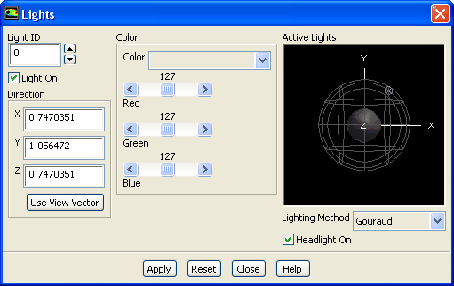
You can also turn on lighting effects using the Lights dialog box (Figure 29.2.9).
 Graphics and Animations
 Lights...
For constant lighting effects in the direction of the view, turn on the Headlight On option in the Lights dialog box. This option has the effect of a light source directly in front of the model, no matter what orientation the model is viewed in. To disable this feature, turn off the Headlight On option in the Lights dialog box.
In the Lighting Method drop-down list, choose Flat, Gouraud, or Phong to enable the appropriate lighting method. (These methods are described above.) To disable lighting, select Off in the list. To see the lighting effects in the active graphics window, click the Apply button.
Defining Light Sources
You can control individual lights in the Lights dialog box (Figure 29.2.9). The Lights dialog box allows you to create a light and then turn it off without deleting it. In this way, you can retain lights that you have defined previously but do not wish to use at present.
 Graphics and Animations
 Lights...
(You can also open the Lights dialog box by clicking on the Lights... button in the Display Options dialog box.)
By default, light 0 is defined to be dark gray with a direction of (1,1,1). A light source is a distant light, similar to the sun. The direction (1,1,1) means that the rays from the light will be parallel to the vector from (1,1,1) to the origin. To create an additional light (e.g., light 1), follow the steps listed below.
Removing a Light
To remove a light, enter the ID number of the light to be removed in the Light ID field and then turn off the Light On button. When a light is turned off, its definition is retained, so you can easily add it to the display again at a later time by turning on the Light On button. For example, you may want to define three different lights to be used in different scenes. You can define each of them, and then turn on only one or two at a time, using the Light ID field and the Light On button. Once you have made all the desired modifications to the lights, remember to click the Apply button to save the changes.
Resetting the Light Definitions
If you have made changes to the light definitions, but you have not yet clicked on Apply, you can reset the lights by clicking on the Reset button. All lighting characteristics will revert to the last saved state (i.e., the lighting that was in effect the last time you opened the dialog box or clicked on Apply).
Previous:
29.2.5 Changing the Colormap