![[ANSYS, Inc. Logo]](fluentlogo.gif)


|
|
|
After the volatile component of the particle is completely evolved, a surface reaction begins which consumes the combustible fraction,
 , of the particle. Law 5 is thus active (for a combusting particle) after the volatiles are evolved:
and until the combustible fraction is consumed:
When the combustible fraction,
 , has been consumed in Law 5, the combusting particle may contain residual "ash'' that reverts to the inert heating law, Law 6 (described previously).
With the exception of the multiple surface reactions model, the surface combustion law consumes the reactive content of the particle as governed by the stoichiometric requirement,
 , of the surface "burnout'' reaction:
where
 is defined in terms of mass of oxidant per mass of char, and the oxidant and product species are defined in the
Set Injection Properties dialog box.
is defined in terms of mass of oxidant per mass of char, and the oxidant and product species are defined in the
Set Injection Properties dialog box.
ANSYS FLUENT provides a choice of four heterogeneous surface reaction rate models for combusting particles:
Each of these models is described in detail below. You will choose the surface combustion model when you are setting physical properties for the combusting-particle material, as described in this section in the separate User's Guide. By default, the diffusion-limited rate model will be used.
The Diffusion-Limited Surface Reaction Rate Model
The diffusion-limited surface reaction rate model which is the default model in ANSYS FLUENT, assumes that the surface reaction proceeds at a rate determined by the diffusion of the gaseous oxidant to the surface of the particle:
| where |
 |
= | diffusion coefficient for oxidant in the bulk (m
 /s) /s) |
 |
= | local mass fraction of oxidant in the gas | |
 |
= | gas density (kg/m
 ) ) | |
 |
= | stoichiometry of Equation 15.4-64 |
Equation 15.4-65 is derived from the model of Baum and Street [ 20] with the kinetic contribution to the surface reaction rate ignored. The diffusion-limited rate model assumes that the diameter of the particles does not change. Since the mass of the particles is decreasing, the effective density decreases, and the char particles become more porous.
The Kinetic/Diffusion Surface Reaction Rate Model
The kinetic/diffusion-limited rate model assumes that the surface reaction rate is determined either by kinetics or by a diffusion rate. ANSYS FLUENT uses the model of Baum and Street [ 20] and Field [ 96], in which a diffusion rate coefficient
and a kinetic rate
are weighted to yield a char combustion rate of
where
 is the surface area of the droplet (
 ),
),
 is the partial pressure of oxidant species in the gas surrounding the combusting particle, and the kinetic rate,
 , incorporates the effects of chemical reaction on the internal surface of the char particle (intrinsic reaction) and pore diffusion. In
ANSYS FLUENT, Equation
15.4-68 is recast in terms of the oxidant mass fraction,
, incorporates the effects of chemical reaction on the internal surface of the char particle (intrinsic reaction) and pore diffusion. In
ANSYS FLUENT, Equation
15.4-68 is recast in terms of the oxidant mass fraction,
 , as
, as
The particle size is assumed to remain constant in this model while the density is allowed to decrease.
When this model is enabled, the rate constants used in Equations 15.4-66 and 15.4-67 are entered in the Create/Edit Materials dialog box, as described in this section in the separate User's Guide.
The Intrinsic Model
The intrinsic model in
ANSYS FLUENT is based on Smith's model [
324], assuming the order of reaction is equal to unity. Like the kinetic/diffusion model, the intrinsic model assumes that the surface reaction rate includes the effects of both bulk diffusion and chemical reaction (see Equation
15.4-69). The intrinsic model uses Equation
15.4-66 to compute the diffusion rate coefficient,
 , but the chemical rate,
 , is explicitly expressed in terms of the intrinsic chemical and pore diffusion rates:
 is the effectiveness factor, or the ratio of the actual combustion rate to the rate attainable if no pore diffusion resistance existed [
182]:
is the effectiveness factor, or the ratio of the actual combustion rate to the rate attainable if no pore diffusion resistance existed [
182]:
 |
(15.4-71) |
where
 is the Thiele modulus:
 is the density of oxidant in the bulk gas (kg/m
 ) and
) and
 is the effective diffusion coefficient in the particle pores. Assuming that the pore size distribution is unimodal and the bulk and Knudsen diffusion proceed in parallel,
 is given by
where
 is the bulk molecular diffusion coefficient and
 is the porosity of the char particle:
 |
(15.4-74) |
 and
and
 are, respectively, the apparent and true densities of the pyrolysis char.
 (in Equation
15.4-73) is the tortuosity of the pores. The default value for
(in Equation
15.4-73) is the tortuosity of the pores. The default value for
 in
ANSYS FLUENT is
in
ANSYS FLUENT is
 , which corresponds to an average intersecting angle between the pores and the external surface of 45
 [
182].
[
182].
 is the Knudsen diffusion coefficient:
where
 is the particle temperature and
 is the mean pore radius of the char particle, which can be measured by mercury porosimetry. Note that macropores (
 Å) dominate in low-rank chars while micropores (
 Å) dominate in high-rank chars [
182].
Å) dominate in high-rank chars [
182].
 (in Equations
15.4-70 and
15.4-72) is the specific internal surface area of the char particle, which is assumed in this model to remain constant during char combustion. Internal surface area data for various pyrolysis chars can be found in [
323]. The mean value of the internal surface area during char combustion is higher than that of the pyrolysis char [
182]. For example, an estimated mean value for bituminous chars is 300 m
(in Equations
15.4-70 and
15.4-72) is the specific internal surface area of the char particle, which is assumed in this model to remain constant during char combustion. Internal surface area data for various pyrolysis chars can be found in [
323]. The mean value of the internal surface area during char combustion is higher than that of the pyrolysis char [
182]. For example, an estimated mean value for bituminous chars is 300 m
 /g [
50].
/g [
50].
 (in Equations
15.4-70 and
15.4-72) is the intrinsic reactivity, which is of Arrhenius form:
(in Equations
15.4-70 and
15.4-72) is the intrinsic reactivity, which is of Arrhenius form:
where the pre-exponential factor
 and the activation energy
 can be measured for each char. In the absence of such measurements, the default values provided by
ANSYS FLUENT (which are taken from a least squares fit of data of a wide range of porous carbons, including chars [
323]) can be used.
can be measured for each char. In the absence of such measurements, the default values provided by
ANSYS FLUENT (which are taken from a least squares fit of data of a wide range of porous carbons, including chars [
323]) can be used.
To allow a more adequate description of the char particle size (and hence density) variation during combustion, you can specify the burning mode
 , relating the char particle diameter to the fractional degree of burnout
 (where
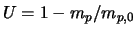 ) by [
322]
) by [
322]
where
 is the char particle mass and the subscript zero refers to initial conditions (i.e., at the start of char combustion). Note that
 where the limiting values 0 and
 correspond, respectively, to a constant size with decreasing density (zone 1) and a decreasing size with constant density (zone 3) during burnout. In zone 2, an intermediate value of
 , corresponding to a decrease of both size and density, has been found to work well for a variety of chars [
322].
, corresponding to a decrease of both size and density, has been found to work well for a variety of chars [
322].
When this model is enabled, the rate constants used in Equations 15.4-66, 15.4-70, 15.4-72, 15.4-73, 15.4-75, 15.4-76, and 15.4-77 are entered in the Create/Edit Materials dialog box, as described in this section in the separate User's Guide.
The Multiple Surface Reactions Model
Modeling multiple particle surface reactions follows a pattern similar to the wall surface reaction models, where the surface species is now a "particle surface species''. For the mixture material defined in the Species Model dialog box, the particle surface species can be depleted or produced by the stoichiometry of the particle surface reaction (defined in the Reactions dialog box). The particle surface species constitutes the reactive char mass of the particle, hence, if a particle surface species is depleted, the reactive "char'' content of the particle is consumed, and in turn, when a surface species is produced, it is added to the particle "char'' mass. Any number of particle surface species and any number of particle surface reactions can be defined for any given combusting particle.
Multiple injections can be accommodated, and combusting particles reacting according to the multiple surface reactions model can coexist in the calculation, with combusting particles following other char combustion laws. The model is based on oxidation studies of char particles, but it is also applicable to gas-solid reactions in general, not only to char oxidation reactions.
See Section 7.3 for information about particle surface reactions.
Limitations
Note the following limitations of the multiple surface reactions model:
Heat and Mass Transfer During Char Combustion
The surface reaction consumes the oxidant species in the gas phase; i.e., it supplies a (negative) source term during the computation of the transport equation for this species. Similarly, the surface reaction is a source of species in the gas phase: the product of the heterogeneous surface reaction appears in the gas phase as a user-selected chemical species. The surface reaction also consumes or produces energy, in an amount determined by the heat of reaction defined by you.
The particle heat balance during surface reaction is
where
 is the heat released by the surface reaction. Note that only a portion (
 ) of the energy produced by the surface reaction appears as a heat source in the gas-phase energy equation: the particle absorbs a fraction
 of this heat directly. For coal combustion, it is recommended that
 be set to 1.0 if the char burnout product is CO and 0.3 if the char burnout product is CO
 [
33].
[
33].
Radiation heat transfer to the particle is included only if you have enabled the P-1 or discrete ordinates radiation model and you have activated radiation heat transfer to particles using the Particle Radiation Interaction option in the Discrete Phase Model dialog box.
By default, Equation 15.4-78 is solved analytically, by assuming that the temperature and mass of the particle do not change significantly between time steps. ANSYS FLUENT can also solve Equation 15.4-78 in conjunction with the equivalent mass transfer equation using a stiff coupled solver. See this section in the separate User's Guide for details.
Previous:
15.4.4 Devolatilization (Law 4)




![D_0 = C_1 \frac{\left [ (T_p + T_{\infty})/2 \right]^{0.75}}{d_p}](img6205.gif)




![\phi = \frac{d_p}{2} \left[ \frac{S_b \rho_p A_g k_i p_{\rm ox}}{D_e \rho_{\rm ox}} \right]^{1/2}](img6220.gif)
![D_e = \frac{\theta}{\tau^2} \left[ \frac{1}{D_{\rm Kn}} + \frac{1}{D_0} \right]^{-1}](img6225.gif)



