![[ANSYS, Inc. Logo]](fluentlogo.gif)


|
|
|
In order to establish the turbomachinery-specific coordinate system used in subsequent postprocessing functions, ANSYS FLUENT requires you to define the topology of the flow domain. The procedure for defining the topology is described below, along with details about the boundary types.
|
|
Note that the current implementation of the turbomachinery topology definition for postprocessing is no longer limited to one row of blades at a time. If your geometry contains multiple rows of blades, you can define all turbomachinery topologies simultaneously. You can name and/or manage all topologies and perform various turbomachinery postprocessing tasks on a single topology or on all topologies at once.
|
|
|
The turbo coordinates can only be generated properly if the correct rotation axis is specified in the boundary conditions dialog box for the fluid zone (see Section
7.2.1).
|
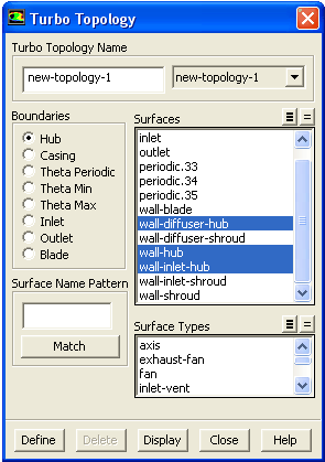
To define the turbomachinery topology in ANSYS FLUENT, you will use the Turbo Topology dialog box (Figure 29.10.1).
Define
 Turbo Topology...
The steps for defining topology for your turbomachinery application are as follows:
If you want to select several surfaces of the same type, you can select that type in the Surface Types list instead. All of the surfaces of that type will be selected automatically in the Surfaces list (or deselected, if they are all selected already). Another shortcut is to specify a Surface Name Pattern and click Match to select surfaces with names that match the specified pattern. For example, if you specify wall*, all surfaces whose names begin with wall (e.g., wall-1, wall-top) will be selected automatically. If they are all selected already, they will be deselected. If you specify wall?, all surfaces whose names consist of wall followed by a single character will be selected (or deselected, if they are all selected already).
|
|
For a complete turbo topology definition the surfaces defined as inlet, outlet, hub, casing, periodic, theta min, and theta max (if available) should form a closed domain.
|
ANSYS FLUENT will inform you that the turbomachinery postprocessing functions have been activated, and the Turbo menu will appear in ANSYS FLUENT's menu bar at the top of the console window.
 . This position vector should be outside the domain, e.g., if your domain lies in the first and second quadrant, specify negative
 axis as the zero
 line. This will ensure that there is no discontinuity in angular coordinates within the domain. This can be done using the
display/set/zero-angle-dir command.
line. This will ensure that there is no discontinuity in angular coordinates within the domain. This can be done using the
display/set/zero-angle-dir command.
 line is
 axis. If this axis passes through the domain, you should define the zero
 line, so as to satisfy above criteria.
|
|
Note that the topology setup that you define will be saved to the case file when you save the current model. Thus, if you read this case back into
ANSYS FLUENT, you do not need to set up the topology again.
|
However, use of a boundary condition file to set the turbo topology for two similar cases may not work properly. In that case you need to set the turbo topology manually.
Boundary Types
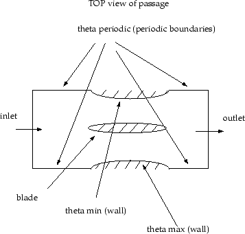
The boundaries for the turbomachinery topology are as follows (see Figure 29.10.2):
 ) positions on a circumferential boundary.
Previous:
29.10 Turbomachinery Postprocessing