[ANSYS, Inc. Logo] return to home search
next up previous contents index

27.9.2 Performing Anisotropic Adaption

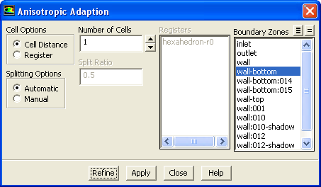
You will perform anisotropic adaption in the Anisotropic Adaption dialog box (Figure  27.9.1).

Adapt $\rightarrow$ Anisotropic...

Figure 27.9.1: The Anisotropic Adaption Dialog Box
figure

The procedure for performing anisotropic adaption is as follows:

1.   In the Anisotropic Adaption dialog box, select Cell Distance or Register as the adaption Cell Options. This allows you to control the marking of boundary layer cells. Select Cell Distance and enter the Number of Cells to be adapted and marked using the distance from the boundary zone. Select Register to adapt and mark cells using an existing Register.

2.    Splitting Options control how the splitting ratio is computed. It is defined as follows:


 splitting \; ratio = \frac{height \; of\; the\; splitting \;... ...;to \;the \;base\; face}{original \;height\; of \;the\; cell}

By default, Automatic is selected, resulting in the ratio being computed automatically from the mesh. If you selected Manual, enter the desired Split Ratio. If you choose to compute the split ratio automatically, the split ratio of the first layer is computed, and it may be 0.5 if the original cells are uniformly distributed, resulting in the height of the first layer being the same as the height of the second layer.

figure   

Note that the Split Ratio that you enter is only applicable to the first layer, and all the other layers are split with a ratio of 0.5.

3.   For the Cell Distance option, one or more boundary face zones must be selected before marking the cells for refinement.

4.   For the Register option, select a register in the list. Note that one or more boundary face zone must be selected before doing the refinement.

5.   Click Refine to refine the marked cells.


next up previous contents index Previous: 27.9.1 Limitations of Anisotropic
Up: 27.9 Anisotropic Adaption
Next: 27.10 Geometry-Based Adaption
Release 12.0 © ANSYS, Inc. 2009-01-29