![[ANSYS, Inc. Logo]](fluentlogo.gif)


|
|
|
This section describes how to set up and apply the inert model. For a discussion about the theory, refer to this section in the separate Theory Guide.
To enable the inert model, make sure that the non-premixed or partially premixed model is selected in the Species Model dialog box, or that a PDF file is read. Refer to Section 16.1 and Section 18 to learn more about these models.
 Models

 Inert
Inert
 Edit...
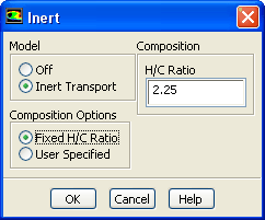
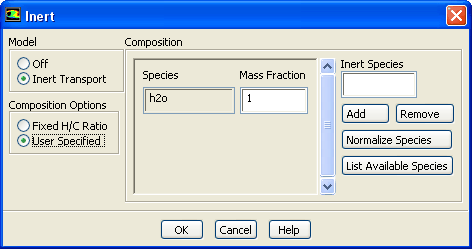
The Inert dialog box will be displayed (Figure 16.7.6). To enable this model, select Inert Transport. The following steps will walk you through setting up the inert model:
 ) enter
4 for
H/C Ratio.
) enter
4 for
H/C Ratio.
Setting the H/C ratio assumes that the burned gas resulted from the complete, stoichiometric combustion of that hydrocarbon fuel with air, and the only products of the combustion are
 ,
,
 and
and
 .
.
You can specify your composition stream by adding or removing species if your stream is composed of species other than the default species list.
Setting Boundary Conditions for Inert Transport
You will need to set appropriate boundary conditions at flow inlets and exits for the inert tracer mass fraction,
 . The tracer species mass fraction must be between zero and one, with the value one meaning that all of the material entering the domain comes from the inert stream. The values for flow boundaries are set in the
Inert Stream field of the inlet boundary condition dialog boxes, under the
Species tab.
. The tracer species mass fraction must be between zero and one, with the value one meaning that all of the material entering the domain comes from the inert stream. The values for flow boundaries are set in the
Inert Stream field of the inlet boundary condition dialog boxes, under the
Species tab.
Initializing the Inert Stream
The main assumption of the inert model is that the composition of the inert stream does not change with combustion. For some dilutants, this is a very reasonable assumption, however, it is not valid for rich combustion where there is fuel in the exhaust stream. For cases where there is fuel or oxidizer left in the exhaust gas, accurate results will depend upon the user taking the fuel or oxidizer species into account when setting initial conditions.
Inert Fraction
Initialization of the inert mass fraction
 is done in the same way as other variables: by entering in the appropriate value in the
Solution Initialization task page. Another option for initialization is to patch the value of
is done in the same way as other variables: by entering in the appropriate value in the
Solution Initialization task page. Another option for initialization is to patch the value of
 in a region of the domain. When the value of
 is patched in this way,
ANSYS FLUENT automatically recalculates the enthalpy field for the current temperature field in order to account for the change in composition.
is patched in this way,
ANSYS FLUENT automatically recalculates the enthalpy field for the current temperature field in order to account for the change in composition.
See Section 26.9.2 for details about patching values of solution variables.
Inert Composition
For combustion calculations which burn a hydrocarbon fuel, ANSYS FLUENT provides a straightforward way of setting the initial composition of the inert stream. The inert composition can be set by assuming a ratio of hydrogen to carbon in the following overall oxidation reaction (from Heywood [ 31]):
which can be rewritten in terms of the ratio of hydrogen to carbon atoms (
 ) in the fuel as
If Equation
16.7-3 is solved for the mass fractions of
 ,
,
 and
and
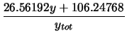
 , the following relations are obtained:
 |
 |
 |
(16.7-4) |
 |
 |
 |
(16.7-5) |
 |
 |
 |
(16.7-6) |
where

Setting the H/C ratio assumes that the burned gas resulted from the complete, stoichiometric combustion of that hydrocarbon fuel, and the only products of the combustion are
 ,
,
 and
and
 . An arbitrary composition for the inert stream can also be specified in the interface.
Previous:
16.7.4 Postprocessing the Look-Up