[ANSYS, Inc. Logo] return to home search
next up previous contents index

14.5 Using the Dual Cell Heat Exchanger Model

The steps for setting up the dual cell heat exchanger model is as follows:

1.   Read the mesh file containing overlapping heat exchanger cores for primary and auxiliary fluids.

2.   Enable the calculation of energy in the Energy dialog box.

figure Models figure figure Energy figure Edit...

3.   Enable the Dual Cell Model in the Heat Exchanger Model dialog box and click Define... (Figure  14.5.1).

figure Models figure figure Heat Exchanger figure Edit...

Figure 14.5.1: The Heat Exchanger Model Dialog Box
figure

4.   Specify the inputs to the dual cell heat exchanger model, using the Dual Cell Heat Exchanger dialog box (Figure  14.5.2).

Figure 14.5.2: The Dual Cell Heat Exchanger Dialog Box
figure

5.   Click New... to define the heat exchanger. The Set Dual Cell Heat Exchanger dialog box will appear (Figure  14.5.3), where you will define the heat exchanger parameters.

Figure 14.5.3: The Set Dual Cell Heat Exchanger Dialog Box
figure

(a)   Enter the heat exchanger Name or keep the default name. The suffix -1 is incremented automatically on defining more than one heat exchanger.

(b)   In the Fluid Zones tab (Figure  14.5.3)

i.   Specify the Number of Passes of your heat exchanger.

ii.   Select the appropriate Primary and Auxiliary Fluid Zone, representing the heat exchanger core.

figure   

The selected zones must be overlapping in physical space.

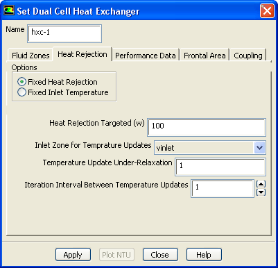
(c)   Click the Heat Rejection tab (Figure  14.5.4).

Figure 14.5.4: The Heat Rejection Tab
figure

i.   If you select Fixed Heat Rejection, set the inputs for the following:

  • Heat Rejection Targeted which is the heat rejection desired from the heat exchanger.

  • Inlet Zone for Temperature Updates allows ANSYS FLUENT to change the temperature of the specified inlet zone in order to match the targeted heat rejection.

  • Temperature Update Under-Relaxation is a factor which controls convergence.

  • Iteration Interval Between Temperature Updates is used to control divergence.

ii.   Select Fixed Inlet Temperature if the output desired is total heat rejection.

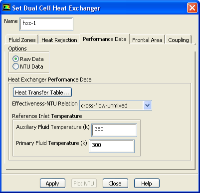
(d)   Click the Performance Data tab (Figure  14.5.5).

Figure 14.5.5: The Performance Data Tab
figure

i.   If you select the Raw Data option, then specify the following:
  • Heat Transfer Table... opens the Heat Transfer Data Table. Populate this table as described in Section  14.3.

  • Effectiveness-NTU Relation computes the NTU values from the heat transfer data. Choose cross-flow-unmixed, parallel-flow, or counter-flow, all of which are described in this section .

  • Auxiliary Fluid Temperature is the inlet reference temperature for the auxiliary fluid.

  • Primary Fluid Temperature is the inlet reference temperature for the primary fluid.

ii.   If you select the NTU Data option, click NTU Table... to access the NTU Table dialog box. Populate this table as described in Section  14.3.

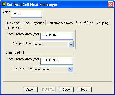
(e)   Click the Frontal Area tab. You have the option to input the Primary and Auxiliary Fluid Core Frontal Area directly, or compute the area from a surface zone, as shown in Figure  14.5.6.

Figure 14.5.6: The Frontal Area Tab
figure

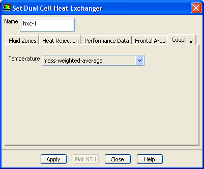
(f)   Click the Coupling tab if you want to couple the heat exchanger passes (Figure  14.5.7).

Figure 14.5.7: The Coupling Tab
figure

Consider the following example illustrating the coupling of a four-pass heat exchanger.

Figure 14.5.8: An Example of a Four-Pass Heat Exchanger
figure

Figure  14.5.8 shows a four-pass heat exchanger with air as the primary fluid and the coolant as the auxiliary fluid. The coolant flows through the tubes in a serpentine manner and air flows normal to the tubes, forming a cross flow pattern. To model this type of flow using the dual cell heat exchanger model, you must first generate the mesh. The mesh should contain the following:

i.   A single primary cell zone.

ii.   Four adjacent auxiliary cell zones, one for each pass. Each auxiliary zone should be separated from the other by a coupled or uncoupled wall. Each pass will have its own inlet and outlet zones.

iii.   The primary and four auxiliary zones should overlap in physical space.

In the Coupling tab, mass-weighted-average is selected by default for the Temperature of the outlet of Pass 1 to the inlet of Pass 2. Similarly, the mass-weighted-average temperature of the outlet of Pass 2 will be applied at the inlet zone of Pass 3, and so on. Alternatively, you can couple the passes by using Profiles... in the Boundary Conditions task page. If you do so, make sure you select none from the Temperature drop-down list in the Coupling tab.

figure   

Make sure to specify the auxiliary zones in the correct order (i.e. the zone for Pass 1 should be selected first, then Pass 2, and so on) in the Fluid Zones tab of the Set Dual Cell Heat Exchanger dialog box.

(g)   Click Apply to save the heat exchanger inputs.

6.   To view the plot of NTU Vs Primary mass flow rate for each auxiliary mass flow rate, click Plot NTU.

The Plot NTU button will plot the performance data curve for the selected heat exchanger. The performance data is supplied through the Performance Data tab.

When you close the Set Dual Cell Heat Exchanger dialog box, you will return to the Dual Cell Heat Exchanger dialog box, where you should now see the heat exchanger name in the Heat Exchanger list.

You can

  • Modify the settings of heat exchanger by selecting it from the list and clicking Modify....

  • Copy the data of one heat exchanger to another using the Copy button, assuming you have more than one heat exchanger.

  • Delete any unwanted heat exchangers by selecting the heat exchanger from the list and clicking Delete.

figure   

All the inputs are copied except for the name, primary fluid zone and auxiliary fluid zone.


next up previous contents index Previous: 14.4.6 Initializing the Auxiliary
Up: 14. Modeling Heat Exchangers
Next: 14.6 Postprocessing for the
Release 12.0 © ANSYS, Inc. 2009-01-29