![[ANSYS, Inc. Logo]](fluentlogo.gif)


|
|
|
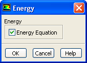
The procedure for setting up a heat transfer problem is described below. (Note that this procedure includes only those steps necessary for the heat transfer model itself; you will need to set up other models, boundary conditions, etc. as usual.)
 Models

 Energy
 Edit...
 Models

 Viscous
 Edit...
As noted in this section in the separate Theory Guide , the viscous heating terms in the energy equation are (by default) ignored by ANSYS FLUENT when the pressure-based solver is used. (They are always included for the density-based solver.) viscous dissipation should be enabled when the shear stress in the fluid is large (e.g., in lubrication problems) and/or in high-velocity, compressible flows (see this equation in the separate Theory Guide).
 Boundary Conditions
At flow inlets and exits you will set the temperature; at walls you may use any of the following thermal conditions:
Section 7.3.14 provides details on the model inputs that govern these thermal boundary conditions. The default thermal boundary condition at inlets is a specified temperature of 300 K; at walls the default condition is zero heat flux (adiabatic). See Chapter 7 for details about boundary condition inputs.
|
|
If your heat transfer application involves two separated fluid regions, see the information provided below.
|
 Materials
Heat capacity and thermal conductivity must be defined, and you can specify many properties as functions of temperature as described in Chapter 8.
|
|
If your heat transfer application involves two separated fluid regions, see the information provided below.
|
Limiting the Predicted Temperature Range: The Temperature Floor and Ceiling
For stability reasons, ANSYS FLUENT includes a limit on the predicted temperature range. The purpose of the temperature ceiling and floor is to improve the stability of calculations in which the temperature should physically lie within known limits. Sometimes intermediate solutions of the equations give rise to temperatures beyond these limits for which property definitions, etc. are not well defined. The temperature limits keep the temperatures within the expected range for your problem. If the ANSYS FLUENT calculation predicts a temperature above the maximum limit, the stored temperature values are "pegged'' at this maximum value. The default for the temperature ceiling is 5000 K. If the ANSYS FLUENT calculation predicts a temperature below the minimum limit, the stored temperature values are "pegged'' at this minimum value. The default for the temperature minimum is 1 K.
If you expect the temperature in your domain to exceed 5000 K, you should use the Solution Limits dialog box to increase the Maximum Temperature.
 Solution Controls
 Limits...
Modeling Heat Transfer in Two Separated Fluid Regions
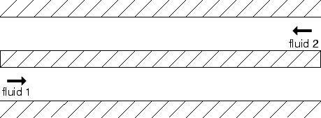
If your heat transfer application involves two fluid regions separated by a solid zone or a wall, as illustrated in Figure 13.2.2, you will need to define the problem with some care. Specifically:
 |
Previous:
13.2 Modeling Conductive and