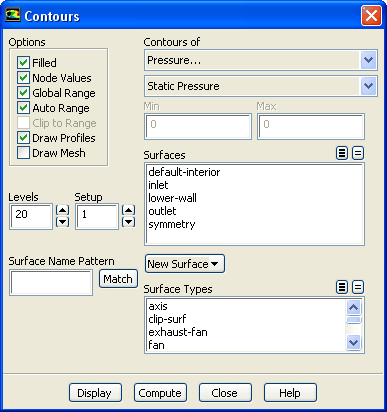
The
Contours dialog box controls the display of contour and profile plots. See Section
29.1.2 for details about the items below.
Controls
Options
contains the check buttons that set various contour display options.
Filled
toggles between filled contours and line contours.
Node Values
toggles between using scalar field values at nodes and at cell centers for computing the contours. When the
Filled option is off,
Node Values is always on. See Section
29.1.2 for details.
Global Range
toggles between basing the minimum and maximum values on the range of values on the selected surfaces (off), and basing them on the range of values in the entire domain (on, the default).
Auto Range
toggles between automatic and manual setting of the contour range. Any time you change the
Contours of selection,
Auto Range is reset to on.
Clip to Range
determines whether or not values outside the prescribed
Min/
Max range are contoured when using
Filled contours. If selected, values outside the range will not be contoured. If not selected, values below the
Min value will be colored with the lowest color on the color scale, and values above the
Max value will be colored with the highest color on the color scale. See Section
29.1.2 for details.
Draw Profiles
causes the addition of a profile plot to the contour plot. The
Profile Options dialog box is opened when
Draw Profiles is selected.
Draw Mesh
toggles between displaying and not displaying the mesh. The
Mesh Display dialog box is opened when
Draw Mesh is selected.
Levels
sets the number of contour levels that are displayed.
Setup
indicates the ID number of the contour setup. For frequently used combinations of contour fields and options, you can store the information needed to generate the contour plot by specifying a
Setup number and setting up the desired information in the
Contours dialog box. See Section
29.1.2 for details.
Surface Name Pattern
specifies the pattern to look for in the names of surfaces. Type the pattern in the text field and click
Match to select (or deselect) the zones in the
Surfaces list with names that match the specified pattern. See Section
29.1.2 for information about matching additional characters using
* and
?.
Contours of
contains a list from which you can select the scalar field to be contoured.
Min
shows the minimum value of the scalar field. If
Auto Range is off, you can set the minimum by typing a new value.
Max
shows the maximum value of the scalar field. If
Auto Range is off, you can set the maximum by typing a new value.
Surfaces
contains a list from which you can select the surfaces on which to draw contours. For 2D cases, if no surface is selected, contouring is done on the entire domain. For 3D cases, you must always select at least one surface.
New Surface
is a drop-down list button that contains a list of surface options:
Surface Types
contains a selectable list of types of surfaces. If you select (or deselect) an item in this list, all surfaces of that type will be selected (or deselected) automatically in the
Surfaces list.
Display
draws the contours in the active graphics window.
Compute
calculates the scalar field and updates the
Min and
Max values (even when
Auto Range is off).
![[ANSYS, Inc. Logo]](fluentlogo.gif)