![[ANSYS, Inc. Logo]](fluentlogo.gif)


|
|
|
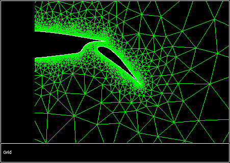
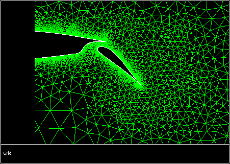
Figure 19.6.1 shows a mesh that was created for solving the flow around a flap airfoil. The mesh is very fine near the surface of the airfoil so that the viscous-affected region may be resolved. However, the mesh grows very rapidly away from the airfoil, because of which the flow separation known to occur on the suction surface of the flap will not be properly predicted. To avoid this problem, the mesh is adapted within circular regions (selected by mouse probe) surrounding the flap. The result is shown in Figure 19.6.2. When the region adaption is performed, the minimum cell volume for adaption is limited (as described in this section in the separate User's Guide) to prevent the very small cells near the surface from being refined further.
Previous:
19.6.1 Defining a Region