![[ANSYS, Inc. Logo]](fluentlogo.gif)


|
|
|
Conservation equations for momentum, mass, and energy for individual parcels in the wall-film are described below. The particle-based approach for thin films was first formulated by O'Rourke [ 257] and most of the following derivation is based closely on that work.
Momentum
The equation for the momentum of a parcel on the film is
 denotes the current face on which the particle resides,
 denotes the current film height at the particle location,
 is the gradient operator restricted to the surface, and
 is the pressure on the surface of the film. On the right-hand side of Equation
15.7-16,
is the pressure on the surface of the film. On the right-hand side of Equation
15.7-16,
 denotes the magnitude of the shear stress of the gas flow on the surface of the film,
 is the unit vector in the direction of the relative motion of the gas and the film surface,
 is the liquid viscosity, and
 is the magnitude of the stress that the wall exerts on the film. Similarly to the expression for
 ,
,
 is the unit vector in the direction of the relative motion of the film and the wall. The remaining expressions on the right-hand side of Equation
15.7-16 are
is the unit vector in the direction of the relative motion of the film and the wall. The remaining expressions on the right-hand side of Equation
15.7-16 are
 which denotes the impingement pressure on the film surface,
 is the impingement momentum source, and
 is the force necessary to keep the film on the surface, as determined by
 is the body force term. Note that the body force term can be very significant, despite the small values of film thickness due to the very high acceleration rates seen in simulations with moving boundaries. The requirement represented by Equation
15.7-17 is explicitly enforced at each time step in
ANSYS FLUENT for all particles representing the wall-film.
is the body force term. Note that the body force term can be very significant, despite the small values of film thickness due to the very high acceleration rates seen in simulations with moving boundaries. The requirement represented by Equation
15.7-17 is explicitly enforced at each time step in
ANSYS FLUENT for all particles representing the wall-film.
The term
 is the surface gradient of the pressure on the face,
 . This pressure,
 , is the sum of the fluid pressure and the impingement pressure from the drops on the face, given by

 is given by
 is the volume of the drop. An approximation of the impingement mass in Equation
15.7-18 is given by
is the volume of the drop. An approximation of the impingement mass in Equation
15.7-18 is given by
 during the time step (
 ). The summation in Equation
15.7-21 is over
all the particles which impinge upon the face during the same interval (
). The summation in Equation
15.7-21 is over
all the particles which impinge upon the face during the same interval (
 ).
).
The expression for the stress that the gas exerts on the surface of the wall-film,
 , in Equation
15.7-16 is given by
, in Equation
15.7-16 is given by

 is the skin friction coefficient and
 is the gas velocity evaluated at the film height above the wall. The assumption made in evaluating the skin friction coefficient is that the wall shear stress from the gas is constant over the thickness of the film and the boundary layer above the film (in the normal direction from the face). The stress is tangent to the wall in the direction of the difference between the wall-film velocity and the gas velocity, so the unit vector in the direction of the velocity difference along the surface is

 is the normal face . The expression for the stress that the wall exerts on the film,
 , in Equation
15.7-16 is given by
, in Equation
15.7-16 is given by

 is the liquid viscosity and
 is the velocity of the wall. Here,
 acts in the direction of the velocity difference between the wall and the film, as given by

 and
and
 , are independent and can point in completely different directions.
Since
ANSYS FLUENT solves a particle position equation of the form

 and
and
 are used from the previous time step and the differential equations for the particle motion are solved with the existing integration routines.
Mass Transfer from the Film
The film vaporization law is applied when the film particle is above the vaporization temperature
 . A wall particle has the temperature limited by the boiling temperature
 and does not have a specific boiling law associated with the physics of film boiling.
The vaporization rate of the film is governed by gradient diffusion from the surface exposed to the gas phase. The gradient of vapor concentration between the film surface and the gas phase is
 |
(15.7-23) |
 is the molar flux of vapor (with units of kgmol/m
 -s),
-s),
 is the mass transfer coefficient (in m/s), and
 and
and
 are the vapor concentrations on the film surface and in the bulk gas, respectively. The units of vapor concentration are kgmol/m
 .
.
The vapor concentration at the surface is evaluated using the saturated vapor pressure at the film surface temperature and the bulk gas concentration is obtained from the flow field solution. The vaporization rate is sensitive to the saturated vapor pressure, similar to droplet vaporization.
The mass transfer coefficient is obtained using a Nusselt correlation for the heat transfer coefficient and replacing the Prandtl number with the Schmidt number. The equation is
For multicomponent vaporization, the Schmidt number based on the diffusivity of each species is used to calculate the correlation in equation 15.7-24 for each component.
The mass of the particle is decreased by
 |
(15.7-25) |
 is the molecular weight of the gas phase species to which the vapor from the liquid is added. The diameter of the film particle is decreased to account for the mass loss in the individual parcel. This keeps the number of drops in the parcel constant and acts only as a place holder. When the parcel detaches from the boundary, the diameter is set to the height of the film and the number in the parcel is adjusted so that the overall mass of the parcel is conserved.
Energy Transfer from the Film
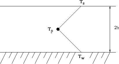
To obtain an equation for the temperature in the film, energy flux from the gas side as well as energy flux from the wall side must be considered. The assumed temperature profile in the liquid is bilinear, with the surface temperature
 being the maximum temperature of the gas at the film height. Furthermore, the boiling point of the liquid and the wall temperature will be the maximum of the wall face temperature
 , and will be the same boiling temperature as the liquid. An energy balance on a film particle yields
 is the conduction from the wall, given by

 is the thermal conductivity of the liquid and
 is the film height at the location of the particle, as seen in Figure
15.7.3. The convection from the top surface,
is the film height at the location of the particle, as seen in Figure
15.7.3. The convection from the top surface,
 is given by

 is the film heat transfer coefficient given by Equation
15.7-24 and
is the film heat transfer coefficient given by Equation
15.7-24 and
 is the area represented by a film particle, taken to be a mass weighted percentage of the face area,
 . Contributions from the impingement terms are neglected in this formulation, as well as contributions from the gradients of the mean temperature on the edges of the film.
Assuming that the temperature changes slowly for each particle in the film, the equation for the change in temperature of a non vaporizing particle can be written as
As the particle trajectory is computed, ANSYS FLUENT integrates Equation 15.7-27 to obtain the particle temperature at the next time value, yielding
![T_p (t + \Delta t) = \alpha_p + [T_p (t) - \alpha_p] e^{-\beta_p \Delta t}](img6494.gif) |
(15.7-28) |
where
 is the integration time step and
 and
and
 are given by
 |
(15.7-30) |
When the particle changes its mass during vaporization, an additional term is added to Equation
15.7-27 to account for the enthalpy of vaporization, which is given by
where
 is the latent heat of vaporization (with units of J/kg) and the expression
 is the rate of evaporation in kg/s. This alters the expression for
 in Equation
15.7-29 so that
in Equation
15.7-29 so that
When the wall-film model is active, the heat flux from the wall to the liquid film is subtracted from the heat flux from the wall to the gas phase. Additionally, enthalpy from vaporization of the liquid from the wall is subtracted from the cell to which the vapor mass goes. Since film boiling is modeled by limiting the liquid phase temperature to the boiling point of the material, energy in excess of that absorbed by the liquid will be put into the gas phase. When the thermal boundary conditions on the wall are set to a constant heat flux, the local temperature of the wall face is used as the thermal boundary condition for the wall-film particles.
|
|
The wall-film model has been specifically implemented for in-cylinder flows and should be used with caution for other applications.
|
Previous:
15.7.4 Separation Criteria









![m_p C_p \frac{ d T_{p}}{ d t} = A_p \left(- \left[ h_f + ... ...appa}{h} \right] T_{p} + h T_g + \frac{\kappa}{h} T_w \right)](img6493.gif)



