![[ANSYS, Inc. Logo]](fluentlogo.gif)


|
|
|
The crevice model implemented in ANSYS FLUENT is a zero-dimensional ring-flow model based on the model outlined in Namazian and Heywood [ 245] and Roberts and Matthews [ 295]. The model is geared toward in-cylinder specific flows, and more specifically, direct-injection (DI) diesel engines , and thus is available only for time-dependent simulations.
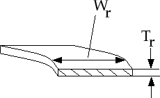
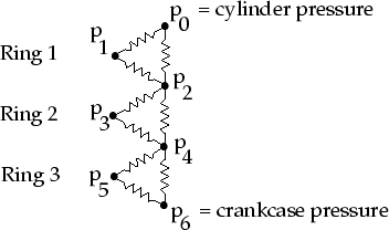
The model takes mass, momentum, and energy from cells adjoining two boundaries and accounts for the storage of mass in the volumes of the crevices in the piston. Detailed geometric information regarding the ring and piston--typically a ring pack around the bore of an engine--is necessary to use the crevice model. An example representation is shown in Figures 12.3.1- 12.3.3.
Model Parameters
 m) in a spark engine (SI) and 4 to 7 mil (100 to 240
 m) in some diesel engines (DI).
 in Figure
12.3.2. Typical values range from 1 to 3 mm for SI engines and 2 to 4 mm for DI engines.
in Figure
12.3.2. Typical values range from 1 to 3 mm for SI engines and 2 to 4 mm for DI engines.
 in Figure
12.3.2. Typical values range from 3 to 3.5 mm for SI engines and 4 to 6 mm for DI diesel engines.
in Figure
12.3.2. Typical values range from 3 to 3.5 mm for SI engines and 4 to 6 mm for DI diesel engines.
 m).
m).
 m).
m).
 m).
m).
The ring pack is the set of rings that seal the piston in the cylinder bore. As the piston moves upward in the cylinder when the valves are closed (e.g., during the compression stroke in a four-stroke cycle engine), the pressure in the cylinder rises and flow begins to move past the rings. The pressure distribution in the ring pack is modeled by assuming either fully-developed compressible flow through the spaces between the rings and the piston, or choked compressible flow between the rings and the cylinder wall.
Since the temperature in the ring pack is fixed and the geometry is known, once a pressure distribution is calculated, the mass in each volume can be found using the ideal gas equation of state. The overall mass flow out of the ring pack (i.e., the flow past the last ring specified) is also calculated at each discrete step in the ANSYS FLUENT solution.
Previous:
12.3 Crevice Model