![[ANSYS, Inc. Logo]](fluentlogo.gif)


|
|
|
Most semiconductor fabrication devices operate far below atmospheric pressure, typically only a few millitorrs. At such low pressures, the fluid flow is in the slip regime and the normally used no-slip boundary conditions for velocity and temperature are no longer valid.
The Knudsen number
, denoted Kn, and defined as the ratio of mean free path to a characteristic length scale of the system, is used to quantify continuum flow regimes. Since the mean free path
increases as the pressure is lowered, the high end of Kn values represents
free molecular flow and the low end the
continuum regime. The range in between these two extremes is called the slip regime (
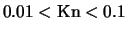 ) [
28] In the slip regime, the gas-phase velocity at a solid surface differs from the velocity at which the wall moves, and the gas temperature at the surface differs from the wall temperature. Maxwell's models are adopted for these physical phenomena in
ANSYS FLUENT for their simplicity and effectiveness.
) [
28] In the slip regime, the gas-phase velocity at a solid surface differs from the velocity at which the wall moves, and the gas temperature at the surface differs from the wall temperature. Maxwell's models are adopted for these physical phenomena in
ANSYS FLUENT for their simplicity and effectiveness.
Here,
 and
and
 represents the velocity component that is parallel and normal to the wall, respectively. The subscripts
 ,
,
 and
and
 indicate gas, wall and cell-center velocities.
 is the distance from cell center to the wall.
 is the momentum accommodation coefficient of the gas mixture and its value is calculated as mass-fraction weighted average of each gas species in the system.
The mean free path,
 , is computed as follows:
 is the Lennard-Jones characteristic length of species
 .
.
 is the Boltzmann constant,
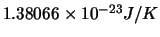 .
.
Equations 7.2-14 and 7.2-15 indicate that while the gas velocity component normal to the wall is the same as the wall normal velocity, the tangential components slip. The values lie somewhere between the cell-center and the wall values. These two equations can be combined to give a generalized formulation:
where
 |
(7.2-20) |
or equivalently
where
 is the thermal accommodation coefficient of the gas mixture and is calculated as
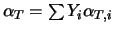 .
.
|
|
The low-pressure slip boundary formulation is available only with the pressure-based solver.
|
Previous:
7.2.2 Reaction-Diffusion Balance for





![\vec{V}_g = \frac{\vec{V}_w + \frac{k}{\delta}[(\vec{V}_w\cd... ...ec{V}_c - (\vec{V}_c\cdot\vec{n})\vec{n}]}{1+\frac{k}{\delta}}](img3303.gif)



