[ANSYS, Inc. Logo] return to home search
next up previous contents

Step 9: Solution: Transient Flow

1.   Modify the plotting of the mass flow rate at the nozzle exit.

figure Monitors (Surface Monitors) figure figure surf-mon-1 figure Edit...

  Because each time step requires 30 iterations, a smoother plot will be generated by plotting at every time step.

figure

(a)   Enter noz_uns.out for File Name.

(b)   Select Time Step from the X Axis drop-down list.

(c)   Select Time Step from the Get Data Every drop-down list.

(d)   Click OK to close the Surface Monitor dialog box.

2.   Save the transient solution case file ( noz_uns.cas).

File $\rightarrow$ Write $\rightarrow$ Case...

3.   Modify the plotting of residuals.

figure Monitors figure figure Residuals figure Edit...

(a)   Make sure Plot is enabled in the Options group box.

(b)   Make sure none is selected from the Convergence Criterion drop-down list.

(c)   Set the Iterations to Plot to 100.

(d)   Click OK to close the Residual Monitors dialog box.

4.   Set the time step parameters.

figure Run Calculation

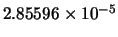
  The selection of the time step is critical for accurate time-dependent flow predictions. Using a time step of $2.85596 \times 10^{-5}$ seconds, 100 time steps are required for one pressure cycle. The pressure cycle begins and ends with the initial pressure at the nozzle exit.

figure

(a)   Enter 2.85596e-5 s for Time Step Size.

(b)   Enter 600 for Number of Time Steps.

(c)   Enter 10 for Max Iterations/Time Step.

(d)   Click Calculate to start the transient simulation.

figure   

Calculating 600 time steps will require significant CPU resources. Instead of calculating the solution, you can read the data file (noz_uns.dat.gz) with the precalculated solution. This data file can be found in the folder where you found the mesh and UDF files.

  By requesting 600 time steps, you are asking ANSYS FLUENT to compute six pressure cycles. The mass flow rate history is shown in Figure  4.6.

Figure 4.6: Mass Flow Rate History (Transient Flow)
figure

5.   Save the transient case and data files ( noz_uns.cas and noz_uns.dat).

File $\rightarrow$ Write $\rightarrow$ Case & Data...


next up previous contents Previous: Step 8: Enable Time
Up: Modeling Transient Compressible Flow
Next: Step 10: Saving and
Release 12.0 © ANSYS, Inc. 2009-02-09