[ANSYS, Inc. Logo] return to home search
next up previous contents

Step 8: Enable Time Dependence and Set Transient Conditions

  In this step you will define a transient flow by specifying a transient pressure condition for the nozzle.

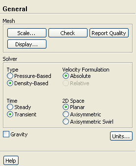
1.   Enable a time-dependent flow calculation.

figure General

figure

(a)   Select Transient in the Time list.

2.   Read the user-defined function (pexit.c), in preparation for defining the transient condition for the nozzle exit.

Define $\rightarrow$ User-Defined $\rightarrow$ Functions $\rightarrow$ Interpreted...

  The pressure at the outlet is defined as a wave-shaped profile , and is described by the following equation:


 p_{\rm exit}(t) = 0.12 \sin (\omega t) + \overline{p}_{\rm exit} (4.12-1)

where


$\omega$ = circular frequency of transient pressure (rad/s)
$\overline{p}_{\rm exit}$ = mean exit pressure (atm)

In this case, $\omega = 2200$ rad/s, and $\overline{p}_{\rm exit} =$ $0.7369$ atm.

A user-defined function (pexit.c) has been written to define the equation (Equation  4.1) required for the pressure profile.

Note:   To input the value of Equation  4.1 in the correct units, the function pexit.c has to be written in SI units.

More details about user-defined functions can be found in the separate UDF Manual.
figure

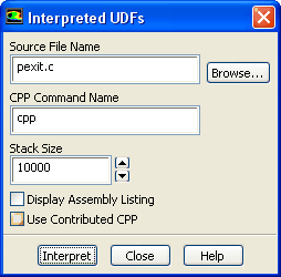
(a)   Enter pexit.c for Source File Name.

(b)   Click Interpret.

  The user-defined function has already been defined, but it needs to be compiled within ANSYS FLUENT before it can be used in the solver.

(c)   Close the Interpreted UDFs dialog box.

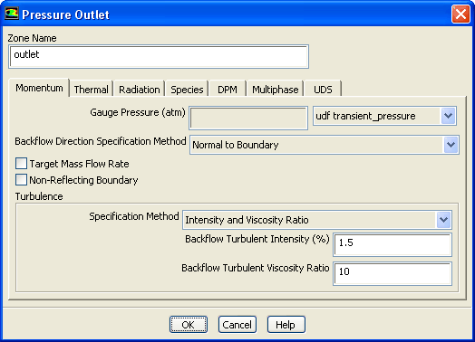
3.   Set the transient boundary conditions at the nozzle exit ( outlet).

figure Boundary Conditions figure figure outlet figure Edit...

figure

(a)   Select udf transient_pressure (the user-defined function) from the Gauge Pressure drop-down list.

(b)   Click OK to close the Pressure Outlet dialog box.

4.   Update the gradient adaption parameters for the transient case.

Adapt $\rightarrow$ Gradient...

(a)   Enter 10 for Interval in the Dynamic group box.

  For the transient case, the mesh adaption will be done every 10 time steps.

(b)   Enter 0.3 for Coarsen Threshold.

(c)   Enter 0.7 for Refine Threshold.

  The refine and coarsen thresholds have been changed during the steady-state computation to meet the limit of 20000 cells. Therefore, you need to reset these parameters to their original values.

(d)   Click Apply to store the values.

(e)   Click Controls... to open the Mesh Adaption Controls dialog box.

i.   Enter 8000 for Min # of Cells.

ii.   Enter 30000 for Max # of Cells.

  You need to increase the maximum number of cells to try to avoid readjustment of the coarsen and refine thresholds. Additionally, you need to limit the minimum number of cells to 8000, because it is not desired to have a coarse mesh during the computation (the current mesh has approximately 20000 cells).

iii.   Click OK to close the Mesh Adaption Controls dialog box.

(f)   Close the Gradient Adaption dialog box.


next up previous contents Previous: Step 7: Solution: Steady
Up: Modeling Transient Compressible Flow
Next: Step 9: Solution: Transient
Release 12.0 © ANSYS, Inc. 2009-02-09