![[ANSYS, Inc. Logo]](fluentlogo.gif)


|
|
|
Now that you have created the mixing elbow geometry, you need to generate a computational mesh throughout the flow volume. For this tutorial, you will use the ANSYS Meshing application to create a mesh for your CFD analysis.
|
|
Note the Refresh Required icon (
 ) within the
Mesh cell for the system. This indicates that the state of the cell requires a refresh and that upstream data has changed since the last refresh or update (e.g., the geometry). Once the mesh is defined, the state of the cell will change accordingly. Likewise for the state of the remaining cells in the system. For more information about system cell states, see the separate
FLUENT in
Workbench User's Guide and the on-line documentation for
ANSYS Workbench. ) within the
Mesh cell for the system. This indicates that the state of the cell requires a refresh and that upstream data has changed since the last refresh or update (e.g., the geometry). Once the mesh is defined, the state of the cell will change accordingly. Likewise for the state of the remaining cells in the system. For more information about system cell states, see the separate
FLUENT in
Workbench User's Guide and the on-line documentation for
ANSYS Workbench.
|
In the ANSYS Workbench Project Schematic, double-click the Mesh cell in the elbow fluid flow analysis system (cell A3). This displays the ANSYS Meshing application with the elbow geometry already loaded. You can also right-click on the Mesh cell to display the context menu where you can select the Edit... option.
|
|
The first time you open the
ANSYS Meshing application, the
Meshing Options are displayed on the right-hand side of the application window where you can set various meshing options. For the purposes of this tutorial, nothing needs be set here, so click
OK to close the
Meshing Options window.
|
In order to simplify your work later on in ANSYS FLUENT, you should label each boundary in the geometry by creating named selections for the pipe inlets, the outlet, and the symmetry surface (the outer wall boundaries are automatically detected by ANSYS FLUENT).
This displays the Selection Name dialog box.
 key and select the individual planes in the graphics window.
|
|
It is important to note that by using the strings "velocity inlet" and "pressure outlet" in the named selections (with or without hyphens or underscore characters),
ANSYS FLUENT automatically detects and assigns the corresponding boundary types accordingly.
|
|
|
Note that since the
ANSYS Meshing application automatically detects that you are going to perform a CFD fluid flow analysis using
ANSYS FLUENT, the
Physics Preference is already set to
CFD and the
Solver Preference is already set to
Fluent.
|
Right-click Mesh in the project Outline tree, and select Update in the context menu.
|
|
Using the
Generate Mesh option creates the mesh, but does not actually create the relevant mesh files for the project and is optional if you already know that the mesh is acceptable. Using the
Update option automatically generates the mesh and creates the relevant mesh files for your project and updates the
ANSYS Workbench cell that references this mesh.
|
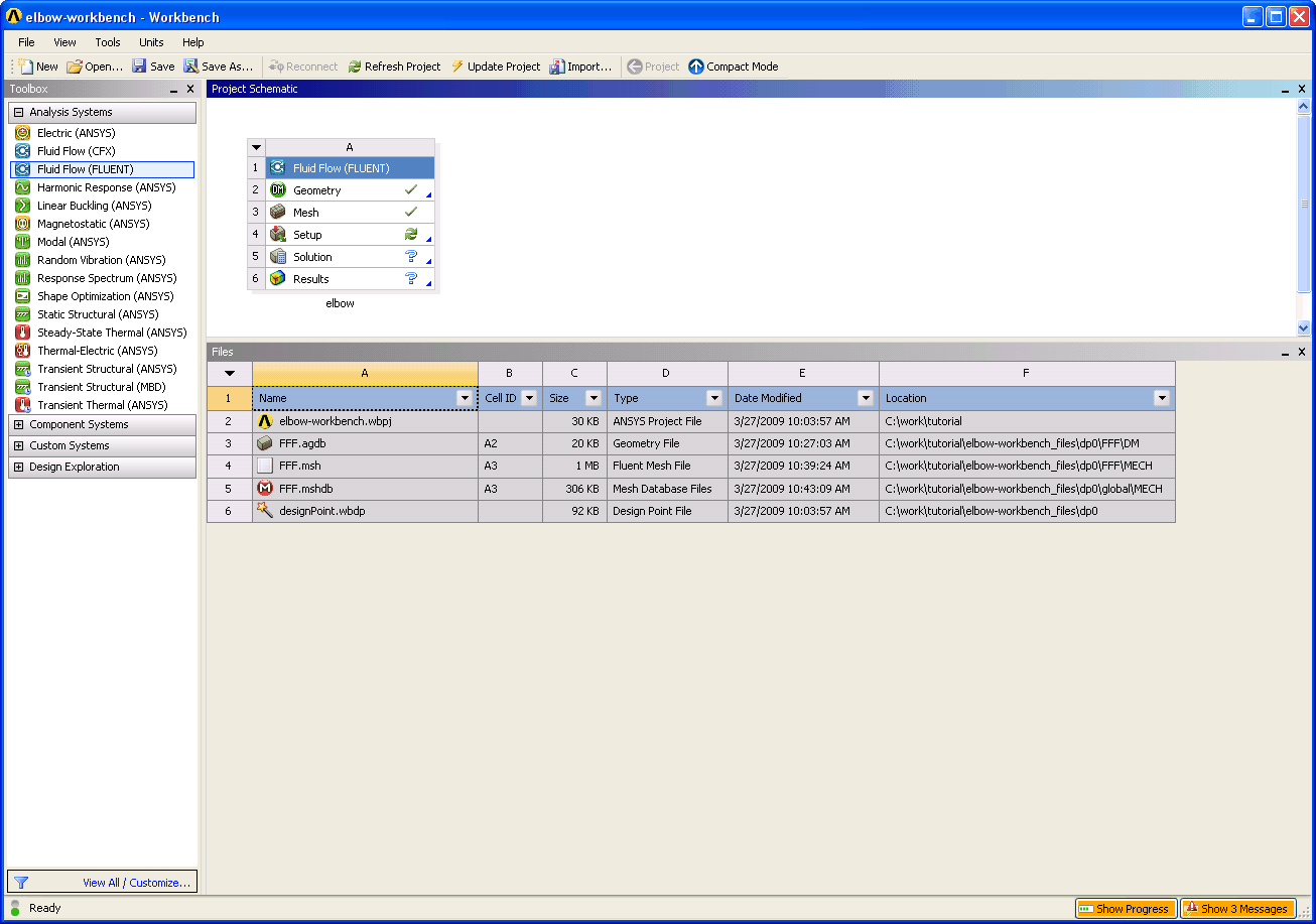
You can simply close the ANSYS Meshing application. ANSYS Workbench automatically saves the mesh and updates the Project Schematic accordingly (the Refresh Required icon in the Mesh cell is replaced by a check mark, indicating that there is a mesh now associated with the fluid flow analysis system).
View
 Files
Files
Note the addition of the mesh files ( FFF.msh and FFF.mshdb) to the list of files. The FFF.msh file is created when you updated the mesh, and the FFF.mshdb file is generated when you close the ANSYS Meshing application.
Previous:
Step 2: Creating the