[ANSYS, Inc. Logo] return to home search
next up previous contents

Step 2: Creating the Geometry in ANSYS DesignModeler

For the geometry of your fluid flow analysis, you can create a geometry in ANSYS DesignModeler, or import the appropriate geometry file. In this tutorial, we will create the geometry from scratch in ANSYS DesignModeler.

figure   

Note the Attention Required icon ( figure ) within the Geometry cell for the system. This indicates that the cell is requires data (e.g., a geometry). Once the geometry is defined, the state of the cell will change accordingly. Likewise for the state of the remaining cells in the system. For more information about system cell states, see the separate FLUENT in Workbench User's Guide and the on-line documentation for ANSYS Workbench.

Note:    If you would rather not create the geometry in ANSYS DesignModeler, you can import a pre-existing geometry by right-clicking the Geometry cell and selecting the Import Geometry option from the context menu. From there, you can browse your file system to locate the elbow-geometry.agdb geometry file that is provided for this tutorial. If you do not have access to ANSYS DesignModeler, you can use the elbow-geometry.stp file instead.

1.   Start ANSYS DesignModeler.

In the ANSYS Workbench Project Schematic, double-click the Geometry cell in the elbow fluid flow analysis system. This displays the ANSYS DesignModeler application. You can also right-click on the Geometry cell to display the context menu where you can select the New Geometry... option.

2.   Set the units in ANSYS DesignModeler.

When ANSYS DesignModeler first appears, you are prompted to select the desired system of length units to work from. For the purposes of this tutorial, where you will create the geometry in inches and perform the CFD analysis using SI units, select Inch as the desired length unit and click OK to close the prompt.

Figure 1.5: Setting the Units in ANSYS DesignModeler
figure

3.   Create the geometry.

The geometry for this tutorial (Figure  1.1) consists of a large curved pipe accompanied by a smaller side pipe. To create the larger main pipe, you will use the Sweep operation. Sweeping requires the use of two sketches: one that defines the profile to be swept (in this case, a half circle since the symmetry of the problem allows you to not have to generate the entire pipe geometry) and the other that defines the path through which the profile is swept.

(a)   Create the profile.

i.   Create a new plane by selecting YZPlane from the Tree Outline and click on New Plane from the Active Plane/Sketch toolbar, near the top of the ANSYS Workbench window. Clicking YZPlane first ensures that the new plane is based on the YZPlane.

figure

ii.   In the Details View for the new plane ( Plane 4), set Transform 1 (RMB) to Offset Global X, and set the Value of the offset to -8 in.

figure

iii.   Click on Generate ( figure located in the ANSYS DesignModeler toolbar) to create the plane.

iv.   Create a new sketch by selecting Plane4 from the Tree Outline and then click New Sketch from the Active Plane/Sketch toolbar, near the top of the ANSYS Workbench window. Clicking the plane first ensures that the new sketch is based on Plane4.

figure

v.   On the Sketching tab, open the Settings toolbox, select Grid, and enable the Show in 2D and the Snap options.

figure

vi.   Set Major Grid Spacing to 1 in and Minor-Steps per Major to 2.

vii.   Zoom in on the center of the grid, so that you can see the grid lines clearly. You can do this by holding down the right-mouse button and dragging a box over the desired viewing area.

viii.   On the Sketching tab, open the Draw toolbox and select Arc by Center (you may need to use the arrows in the toolbox to scroll down to see the correct tool). Draw an arc with a radius of 2 in, centered on $X=-6$ in, $Y=0$ in (located below the origin of Plane4). The grid settings that you have just set up will help you to position the arc and set its radius correctly.

ix.   On the Sketching tab open the Draw toolbox and select Line (you may need to use the arrows in the toolbox to scroll up to see the correct tool). Draw a line from $X=-4$ in, $Y=0$ in to $X=-8$ in, $Y=0$ in.

Figure 1.6: Creating the Arc Profile
figure

(b)   Create the path.

i.   On the Modeling tab select XYPlane, then click New Sketch and then Generate to create a new sketch based on the XYPlane.

ii.   On the Sketching tab, open the Settings toolbox, select Grid, and enable the Show in 2D and the Snap options.

iii.   Set Major Grid Spacing to 1 in and Minor-Steps per Major to 2.

iv.   In the Draw toolbox, select Line to draw two straight lines on the sketch. For reference, the coordinates of the endpoints of the lines are ( $X=-8$ in, $Y=-6$ in), ( $X=0$ in, $Y=-6$ in) for the horizontal line and ( $X=6$ in, $Y=0$ in), ( $X=6$ in, $Y=8$ in) for the vertical line.

v.   In the Draw toolbox, select Arc by Center and click once on the origin (center of the arc). Now select one of the end points of the arc, and then move the mouse around to the other end point and click on it to draw the quarter-circle. If the wrong part of the arc is drawn (that is, a 270 degree segment instead of a 90 segment), click Undo from the Undo/Redo toolbar and try again, making sure that after you click on the first end point, that you move the mouse in the correct direction for the arc that is to be drawn.

Figure 1.7: Creating the Elbow Path
figure

(c)   Create the pipe.

i.   Select Sweep from the 3D Features toolbar.

ii.   Set the Profile to be Sketch1: click on Sketch1 in the Tree Outline and then click on Apply in the Details View at the bottom-left of the screen.

iii.   Set the Path to Sketch2: click on the Not selected text next to Path, click on Sketch2 in the Tree Outline, and then click Apply.

iv.   Click on Generate to create the pipe.

Figure 1.8: Generating the Pipe
figure

(d)   Create the side pipe.

i.   Create a new plane based on the ZXPlane: as before, first make ZXPlane active by clicking on it, then use New Plane to create the plane based upon it.

ii.   In the Details View, set Transform 1 (RMB) to Offset Global X, and set the Value of the offset to 5.5 in.

iii.   Set Transform 2 to Offset Global Y and the Value of the offset to -9 in.

iv.   Click on Generate to create the plane.

v.   With the new plane selected in the Tree Outline, create a New Sketch.

vi.   On the Sketching tab, open the Draw toolbox and select Arc by Center to create the arc centered on the origin with a radius of 0.5 in. Create the arc initially with any convenient radius, and then open the Dimensions toolbox and select Radius to specify the radius more precisely.

vii.   On the Sketching tab, open the Draw toolbox and select Line. Draw a line connecting the open ends of the arc.

viii.   Select Extrude from the 3D Features toolbar.

ix.   Set Base Object to be the new sketch ( Sketch3), and set Operation to Add Material.

x.   Set Direction to Normal and Extent Type to Fixed. Set Depth to 4 in.

xi.   Click on Generate to create the side-pipe.

Figure 1.9: Generating the Additional Pipe
figure

(e)   Specify the geometry as a fluid body.

i.   In the Tree Outline, open the 1 Part, 1 Body branch and select Solid branch.

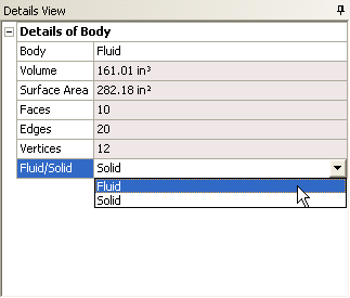
ii.   In the Details View of the body, change the name of the Body from Solid to Fluid.

iii.   Change the Fluid/Solid property from Solid to Fluid.

figure

iv.   Click on Generate.

4.   Close ANSYS DesignModeler.

You can simply close the ANSYS DesignModeler application. ANSYS Workbench automatically saves the geometry and updates the Project Schematic accordingly (the question mark in the Geometry cell is replaced by a check mark, indicating that there is a geometry now associated with the fluid flow analysis system).

5.   View the files generated by ANSYS Workbench.

Figure 1.10: ANSYS Workbench Displaying the Files View for the Project After Creating the Geometry
figure

Note the addition of the geometry file ( FFF.agdb, where FFF indicates a FLUENT-based fluid flow system) to the list of files. If you had imported the geometry file provided for this tutorial (rather than creating the geometry from scratch), the elbow-geometry.agdb (or the elbow-geometry.stp) file would be listed instead.


next up previous contents Previous: Step 1: Creating a
Up: Introduction to Using ANSYS
Next: Step 3: Meshing the
Release 12.1 © ANSYS, Inc. 2009-09-08