If you are using the parallel version of
ANSYS FLUENT (see Chapter
32), you may find it useful to create data surfaces defined by the boundaries of mesh partitions. As described in Section
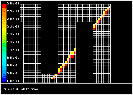
32.5, partitioning the mesh divides it into groups of cells that can be solved on separate processors when you use a parallel solver. A partition surface will contain faces or cells on the boundary of two mesh partitions. For example, you can plot solution values on the partition surface to determine how the solution is changing across a partition interface. Figure
28.3.1 shows cell-partition contours on a partition surface which is overlaid on the mesh.
Figure 28.3.1: Contours of Cell Partitions on Partition Surface Overlaid on Mesh
 |
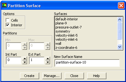
To create a partition surface, you will use the
Partition Surface dialog box (Figure
28.3.2).
Surface
 Partition...
Figure 28.3.2: The
Partition Surface Dialog Box
 |
The steps for creating the partition surface are as follows:
- 1.
Specify the partition boundary you are interested in by indicating the two bordering partitions under the
Partitions heading. The boundary that defines the partition surface is the boundary between the "interior partition'' and the "exterior partition''.
Int Part indicates the ID number of the interior partition (i.e., the partition under consideration), and
Ext Part indicates the ID number of the bordering (exterior) partition. The
Min and
Max fields will indicate the minimum and maximum ID numbers of the mesh partitions. (The minimum is always zero, and the maximum is one less than the number of processors.) If there are more than two mesh partitions, each interior partition will share boundaries with several exterior partitions. By setting the appropriate values for
Int Part and
Ext Part, you can create surfaces for any of these boundaries.
- 2.
Choose interior or exterior faces or cells to be contained in the partition surface by turning
Cells and
Interior on or off under
Options. To obtain a surface consisting of cells that are on the "interior'' side of the partition boundary, turn on both
Cells and
Interior. To create one consisting of cells that are on the "exterior'' side, turn on
Cells and turn off
Interior. If you want the surface to contain the faces on the boundary instead of the cells, turn off the
Cells option. To have the faces reflect data values for the interior cells, turn the
Interior check button on, and to have them reflect values for the exterior cells, turn it off.
- 3.
If you do not want to use the default name assigned to the surface, enter a new name under
New Surface Name. The default name is the concatenation of the surface type and an integer which is the new surface ID (e.g.,
partition-surface-6). (If the
New Surface Name you enter is the same as the name of a surface that already exists,
ANSYS FLUENT will automatically assign the default name to the new surface when it is created.)
|
-

|
The surface name that you enter must begin with an alphabetical letter. If your surface name begins with any other character or number,
ANSYS FLUENT will not accept the entry.
|
- 4.
Click on the
Create button. The new surface name will be added to the
Surfaces list in the dialog box.
If you want to delete or otherwise manipulate any surfaces, click on the
Manage... button to open the
Surfaces dialog box. See Section
28.11 for details.


 Previous:
28.2 Zone Surfaces
Previous:
28.2 Zone Surfaces
Up:
28. Creating Surfaces for
Next:
28.4 Point Surfaces
Release 12.0 © ANSYS, Inc. 2009-01-29 ![[ANSYS, Inc. Logo]](fluentlogo.gif)

