Step 5: Boundary Conditions
Boundary Conditions
1. Set the boundary conditions for
pressure-far-field-1
.
Boundary Conditions
pressure-far-field-1
Edit...
(a) Retain the default value of
0
Pa for
Gauge Pressure
.
(b) Enter
0.8
for
Mach Number
.
(c) Enter
0.997564
and
0.069756
for the
X-Component of Flow Direction
and
Y-Component of Flow Direction
, respectively.
These values are determined by the
angle of attack:
and
.
(d) Select
Turbulent Viscosity Ratio
from the
Specification Method
drop-down list in the
Turbulence
group box.
(e) Retain the default value of
10
for
Turbulent Viscosity Ratio
.
The viscosity ratio should be between 1 and 10 for external flows.
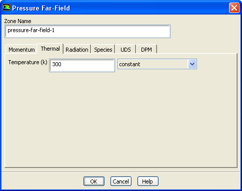
(f) Click the
Thermal
tab and retain the default value of
300
K for
Temperature
.
(g) Click
OK
to close the
Pressure Far-Field
dialog box.
Previous:
Step 4: Materials
Up:
Modeling External Compressible Flow
Next:
Step 6: Operating Conditions
Release 12.0 ©
ANSYS, Inc.
2009-02-09
![[ANSYS, Inc. Logo]](fluentlogo.gif)


 Boundary Conditions

 Boundary Conditions

 pressure-far-field-1
 Edit...

 angle of attack:
 and
and
 .
.  Previous:
Step 4: Materials
Previous:
Step 4: Materials