- 1.
Set the boundary conditions for the inlet (
rotor-inlet).
 Boundary Conditions

 rotor-inlet
 Edit...
- (a)
Enter
1.0 atm for
Gauge Total Pressure.
- (b)
Enter
0.9 atm for
Supersonic/Initial Gauge Pressure.
- (c)
Click the
Thermal tab and enter
288 K for
Total Temperature.
- (d)
Click
OK to close the
Pressure Inlet dialog box.
- 2.
Set the boundary conditions for the outlet (
stator-outlet).
 Boundary Conditions

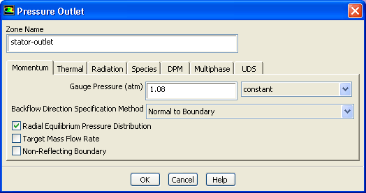
 stator-outlet
 Edit...
- (a)
Enter
1.08 atm for
Gauge Pressure.
- (b)
Enable
Radial Equilibrium Pressure Distribution.
- (c)
Click the
Thermal tab and enter
288 K for
Backflow Total Temperature.
- (d)
Click
OK to close the
Pressure Outlet dialog box.
-
Note:
The momentum settings and temperature you input at the pressure outlet will be used only if flow enters the domain through this boundary. It is important to set reasonable values for these downstream scalar values, in case flow reversal occurs at some point during the calculation.
- 3.
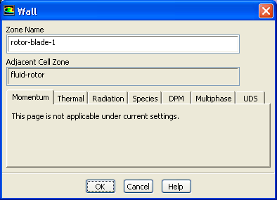
Retain the default boundary conditions for all wall zones.
 Boundary Conditions

 rotor-blade-1
 Edit...
-
Note:
For wall zones,
ANSYS FLUENT always imposes zero velocity for the normal velocity component, which is required whether or not the fluid zone is moving. This condition is all that is required for an inviscid flow, as the tangential velocity is computed as part of the solution.
![[ANSYS, Inc. Logo]](fluentlogo.gif)


 Boundary Conditions