[ANSYS, Inc. Logo] return to home search
next up previous contents

Step 5: Cell Zone Conditions

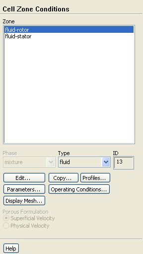
figure Cell Zone Conditions

figure

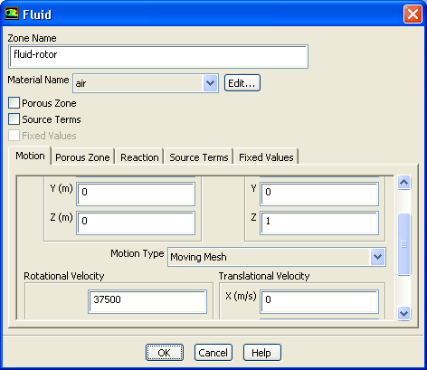
1.   Set the boundary conditions for the fluid in the rotor ( fluid-rotor).

figure Cell Zone Conditions figure figure fluid-rotor figure Edit...

figure

(a)   Retain the default values of ( 0, 0, 1) for X, Y, and Z in the Rotation-Axis Direction group box.

(b)   Select Moving Mesh from the Motion Type drop-down list.

(c)   Enter 37500 rpm for Speed in the Rotational Velocity group box.

  Scroll down to find the Speed number-entry box.

(d)   Click OK to close the Fluid dialog box.

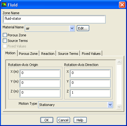
2.   Set the boundary conditions for the fluid in the stator ( fluid-stator).

figure Cell Zone Conditions figure figure fluid-stator figure Edit...

figure

(a)   Retain the default values of ( 0, 0, 1) for X, Y, and Z in the Rotation-Axis Direction group box.

(b)   Retain the default selection of Stationary from the Motion Type drop-down list.

(c)   Click OK to close the Fluid dialog box.

next up previous contents Previous: Step 4: Materials
Up: Using Sliding Meshes
Next: Step 6: Boundary Conditions
Release 12.0 © ANSYS, Inc. 2009-02-09