- 1.
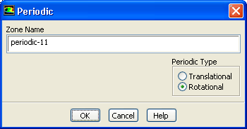
Specify rotational periodicity for the periodic boundary of the rotor (
periodic-11).
 Boundary Conditions

 periodic-11
 Edit...
- (a)
Select
Rotational in the
Periodic Type list.
- (b)
Click
OK to close the
Periodic dialog box.
- 2.
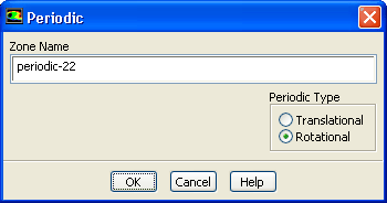
Specify rotational periodicity for the periodic boundary of the stator (
periodic-22).
 Boundary Conditions

 periodic-22
 Edit...
- (a)
Select
Rotational in the
Periodic Type list.
- (b)
Click
OK to close the
Periodic dialog box.
- 3.
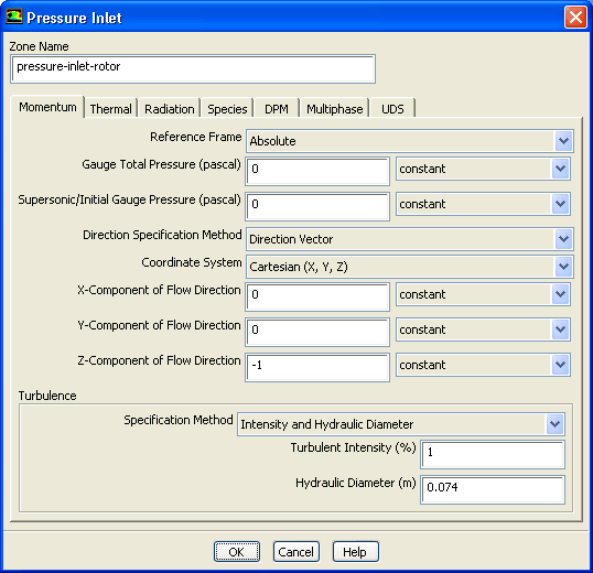
Set the conditions for the pressure inlet of the rotor (
pressure-inlet-rotor).
 Boundary Conditions

 pressure-inlet-rotor
 Edit...
- (a)
Select
Direction Vector from the
Direction Specification Method drop-down list.
- (b)
Enter
0 for
X-Component of Flow Direction.
- (c)
Enter
-1 for
Z-Component of Flow Direction.
- (d)
Select
Intensity and Hydraulic Diameter from the
Specification Method drop-down list.
- (e)
Enter
1% for
Turbulence Intensity and
0.074 m for
Hydraulic Diameter.
-
You will use
 gauge to model ambient conditions. The turbulence level is assumed to be low (1%) and the hydraulic diameter is used as the length scale.
- (f)
Click
OK to close the
Pressure Inlet dialog box.
- 4.
Retain the default settings for the pressure inlet of the stator (
pressure-inlet-stator).
 Boundary Conditions

 pressure-inlet-stator
 Edit...
-
The profiles computed at the rotor outlet are used to update the boundary conditions at the stator inlet. These profiles were set automatically when the mixing plane was created. Therefore, you do not need to set any parameters in this dialog box.
- (a)
Click
OK to close the
Pressure Inlet dialog box.
- 5.
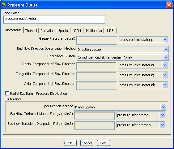
Retain the default settings for the pressure outlet of the rotor (
pressure-outlet-rotor).
 Boundary Conditions

 pressure-outlet-rotor
 Edit...
-
The
Backflow Direction Specification Method was set to
Direction Vector when you created the mixing plane, and the
Coordinate System to
Cylindrical (like for the stator inlet ). The values for the direction cosines are taken from the profiles at the stator.
- (a)
Click
OK to close the
Pressure Outlet dialog box.
- 6.
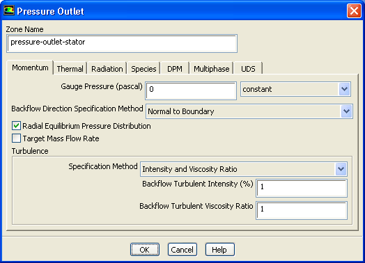
Set the conditions for the pressure outlet of the stator (
pressure-outlet-stator).
 Boundary Conditions

 pressure-outlet-stator
 Edit...
- (a)
Retain the default
Backflow Direction Specification Method.
-
In problems where a backflow exists at the pressure outlet boundary (e.g., torque-converter), you can use this option to specify the direction of the backflow.
- (b)
Enable
Radial Equilibrium Pressure Distribution.
-
Radial equilibrium is used to simulate the pressure distribution which exists due to rotation according to
where
 is the tangential velocity. This is a good approximation for axial flow configurations with relatively straight flow paths (i.e., little change in radius from inlet to exit).
- (c)
Select
Intensity and Viscosity Ratio from the
Specification Method drop-down list.
- (d)
Enter
1% for
Backflow Turbulent Intensity.
- (e)
Enter
1 for
Backflow Turbulent Viscosity Ratio.
- (f)
Click
OK to close the
Pressure Outlet dialog box.
- 7.
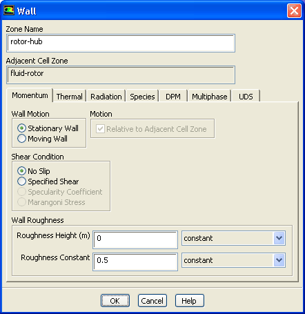
Retain the default conditions for the
rotor-hub.
 Boundary Conditions

 rotor-hub
 Edit...
-
For a rotating reference frame,
ANSYS FLUENT assumes by default that walls rotate with the rotating reference frame, and hence are stationary with respect to it. Since the
rotor-hub is rotating, you should retain the default settings.
- (a)
Click
OK to accept the default settings and close the
Wall dialog box.
- 8.
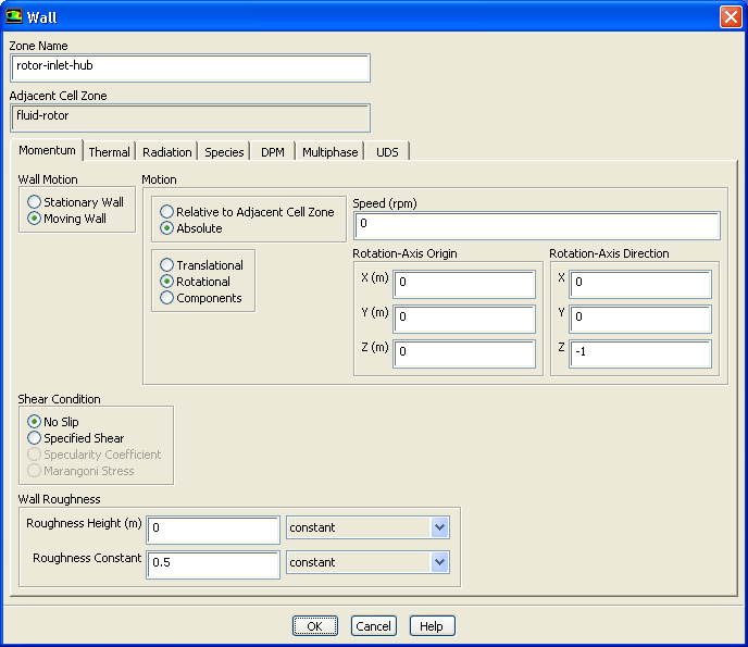
Set the conditions for the inlet hub of the rotor (
rotor-inlet-hub).
 Boundary Conditions

 rotor-inlet-hub
 Edit...
- (a)
Select
Moving Wall in the
Wall Motion list.
-
The
Wall dialog box will expand to show the wall motion inputs.
- (b)
Select
Absolute and
Rotational in the
Motion group box.
- (c)
Enter
-1 for
Z in the
Rotation-Axis Direction group box.
- (d)
Click
OK to close the
Wall dialog box.
-
These conditions set the
rotor-inlet-hub to be a stationary wall in the absolute frame.
- 9.
Set the conditions for the shroud of the rotor inlet (
rotor-inlet-shroud).
 Boundary Conditions

 rotor-inlet-shroud
 Edit...
- (a)
Select
Moving Wall in the
Wall Motion list.
- (b)
Select
Absolute and
Rotational in the
Motion group box.
- (c)
Enter
-1 for
Z in the
Rotation-Axis Direction group box.
- (d)
Click
OK to close the
Wall dialog box.
-
These conditions will set the
rotor-inlet-shroud to be a stationary wall in the absolute frame.
- 10.
Set the conditions for the rotor shroud (
rotor-shroud).
 Boundary Conditions

 rotor-shroud
 Edit...
- (a)
Select
Moving Wall in the
Wall Motion list.
- (b)
Select
Absolute and
Rotational in the
Motion group box.
- (c)
Enter
-1 for
Z in
Rotation-Axis Direction group box.
- (d)
Click
OK to close the
Wall dialog box.
-
These conditions will set the
rotor-shroud to be a stationary wall in the absolute frame.
![[ANSYS, Inc. Logo]](fluentlogo.gif)


 Boundary Conditions