- 1.
Change
wall-2 type to
interior.
 Boundary Conditions

 wall-2
-
The zones
wall-2 and
wall-3 are the interfaces between the three fluid zones. They need to be changed to type
interior, as discussed earlier. The resulting
interior faces are those that have fluid cells on both sides but do not require any boundary conditions to be set.
- (a)
Select
interior from the
Type drop-down list.
-
A
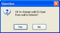
Question dialog box will open, asking if you want to change the type from
wall to
interior.
- i.
Click
Yes to open the
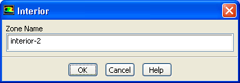
interior dialog box.
-
ANSYS FLUENT will fuse
wall-2 and
wall-2-shadow together to form
interior-2.
- ii.
Click
OK to retain the default
Zone Name.
- (b)
Similarly, change
wall-3 to an interior zone named
interior-3.
- 2.
Identify the rotating fluid zone
(i.e., the zone containing the blades) by displaying the mesh for each zone.
 Boundary Conditions
 Display Mesh...
-
It is unclear when you read the mesh which fluid zone corresponds to which interior zone. While the interior zones can be selected individually in the
Mesh Display dialog box, the fluid zones cannot. Commands in the text
interface, however, can be used to make this association.
- (a)
Deselect all the surfaces by clicking the
 button to the right of the
Surfaces selection list.
button to the right of the
Surfaces selection list.
- (b)
Click the
Outline button to select only the outline surfaces of the domain.
- (c)
Click
Display.
-
Only the domain boundaries and interior walls will be displayed.
- (d)
Type the commands, in the console, as shown.
-
Hint:
You may need to press the
<Enter> key to get the
 prompt.
> display

/display> zone-mesh

()
zone id/name(1) [()] 13

zone id/name(2) [()] <Enter>
|
-
The resulting display (Figure
10.3) shows that zone
fluid-13 corresponds to the rotating region.
- (e)
Close the
Mesh Display dialog box.
Figure 10.3: Mesh in
fluid-13
 |
- 3.
Set the boundary conditions (see Figure
10.1) for the flow inlet (
pressure-inlet-5).
 Boundary Conditions

 pressure-inlet-5
 Edit...
- (a)
Enter
200 Pa for
Gauge Total Pressure.
- (b)
Select
Intensity and Hydraulic Diameter from the
Specification Method drop-down list.
- (c)
Enter
5 % for
Turbulent Intensity.
- (d)
Enter
0.05 m for
Hydraulic Diameter.
- (e)
Click
OK to close the
Pressure Inlet dialog box.
-
Note:
All pressures that you specify in
ANSYS FLUENT are gauge pressures, relative to the operating pressure specified in the
Operating Conditions dialog box. By default, the operating pressure is 101325 Pa.
For details, see
this section in the separate
User's Guide.
- 4.
Set the backflow
turbulence parameters for the flow outlet (
pressure-outlet-9) to the same values used for
pressure-inlet-5.
-
Note:
The backflow values are used only if reversed flow occurs at the outlet, but it is a good idea to use reasonable values, even if you do not expect any backflow to occur.
- 5.
Define the velocity of the wall zone representing the blades (
wall-7) relative to the moving fluid zone.
 Boundary Conditions

 wall-7
 Edit...
-
With
fluid-13 set to a rotating
reference frame,
wall-7 becomes a moving
wall.
- (a)
Select
Moving Wall in the
Wall Motion list.
-
The
Wall dialog box will expand to show the wall motion parameters.
- (b)
Retain the default selection of
Relative to Adjacent Cell Zone and select
Rotational in the
Motion group box.
- (c)
Retain the default value of
0 rad/s for (relative)
Speed.
- (d)
Click
OK to close the
Wall dialog box.
-
The
Rotation-Axis Origin should be located at
 = 0 m and
 = 0 m. With these settings, the blades will move at the same speed as the surrounding fluid.
![[ANSYS, Inc. Logo]](fluentlogo.gif)


 Boundary Conditions