- 1.
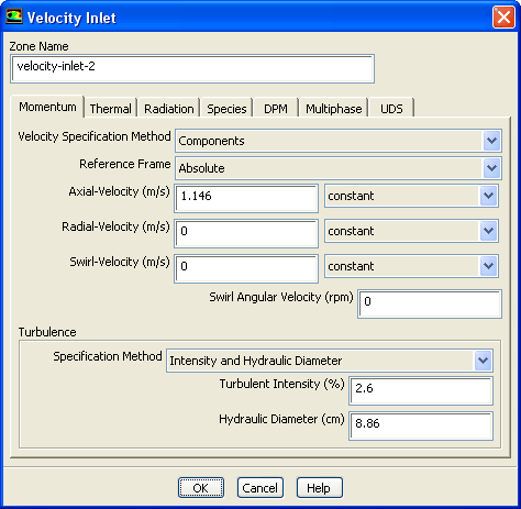
Set the following conditions at the flow inlet (
velocity-inlet-2).
 Boundary Conditions

 velocity-inlet-2
 Edit...
- (a)
Select
Components from the
Velocity Specification Method drop-down list.
- (b)
Enter
1.146 m/s for
Axial-Velocity.
- (c)
Select
Intensity and Hydraulic Diameter from the
Specification Method drop-down list in the
Turbulence group box.
- (d)
Enter
2.6% for
Turbulent Intensity.
- (e)
Enter
8.86 cm for
Hydraulic Diameter.
- (f)
Click
OK to close the
Velocity Inlet dialog box.
- 2.
Set the following conditions at the flow outlet (
pressure-outlet-3).
 Boundary Conditions

 pressure-outlet-3
 Edit...
- (a)
Retain the default selection of
Normal to Boundary from the
Backflow Direction Specification Method drop-down list.
- (b)
Select
Intensity and Viscosity Ratio from the
Specification Method drop-down list in the
Turbulence group box.
- (c)
Enter
5% for
Backflow Turbulent Intensity.
- (d)
Retain the default value of
10 for
Backflow Turbulent Viscosity Ratio.
- (e)
Click
OK to close the
Pressure Outlet dialog box.
-
Note:
ANSYS FLUENT will use the backflow
conditions only if the fluid is flowing into the computational domain through the outlet. Since backflow might occur at some point during the solution procedure, you should set reasonable backflow conditions to prevent convergence from being adversely affected.
- 3.
Accept the default settings for the disk walls (
wall-6).
 Boundary Conditions

 wall-6
 Edit...
- (a)
Click
OK to close the
Wall dialog box.
-
Note:
For a rotating reference
frame,
ANSYS FLUENT assumes by default that all walls rotate at the speed of the moving reference frame, and hence are moving with respect to the stationary (absolute) reference frame. To specify a non-rotating wall, you must specify a rotational speed of 0 in the absolute frame.
![[ANSYS, Inc. Logo]](fluentlogo.gif)


 Boundary Conditions