- 1.
Set the boundary conditions for the streamwise flow inlet (
velocity-inlet-1).
 Boundary Conditions

 velocity-inlet-1
 Edit...
- (a)
Change the
Zone Name from
velocity-inlet-1 to
velocity-inlet-duct.
- (b)
Enter
20 m/s for the
Velocity Magnitude.
- (c)
Select
Intensity and Hydraulic Diameter from the
Specification Method drop-down list in the
Turbulence group box.
- (d)
Enter
1% and
5 in for the
Turbulent Intensity and the
Hydraulic Diameter, respectively.
- (e)
Click the
Thermal tab and enter
450 K for the
Temperature.
- (f)
Click
OK to close the
Velocity Inlet dialog box.
- 2.
Set the boundary conditions for the first injected stream inlet (
velocity-inlet-5).
 Boundary Conditions

 velocity-inlet-5
 Edit...
- (a)
Change the
Zone Name from
velocity-inlet-5 to
velocity-inlet-plenum1.
- (b)
Enter
0.4559 m/s for the
Velocity Magnitude.
- (c)
Select
Intensity and Viscosity Ratio from the
Specification Method drop-down list in the
Turbulence group box.
- (d)
Enter
1% for
Turbulent Intensity and retain the default setting of
10 for
Turbulent Viscosity Ratio.
- (e)
Click the
Thermal tab and retain the setting of
300 K for
Temperature.
- (f)
Click
OK to close the
Velocity Inlet dialog box.
-
In the absence of any identifiable length scale for turbulence, the
Intensity and Viscosity Ratio method should be used.
For more information about setting the boundary conditions for turbulence, see
this chapter in the separate
User's Guide.
- 3.
Copy the boundary conditions set for the first injected stream inlet.
 Boundary Conditions

 velocity-inlet-plenum1
 Copy...
- (a)
Select
velocity-inlet-plenum1 in the
From Boundary Zone selection list.
- (b)
Select
velocity-inlet-6 in the
To Boundary Zones selection list.
- (c)
Click
Copy.
-
A
Warning dialog box will open, asking if you want to copy
velocity-inlet-plenum1 boundary conditions to
(velocity-inlet-6). Click
OK.
- (d)
Close the
Copy Conditions dialog box.
|
-

|
Copying a boundary condition does not create a link from one zone to another. If you want to change the boundary conditions on these zones, you will have to change each one separately.
|
- 4.
Set the boundary conditions for the second injected stream inlet (
velocity-inlet-6).
 Boundary Conditions

 velocity-inlet-6
 Edit...
- (a)
Change the
Zone Name from
velocity-inlet-6 to
velocity-inlet-plenum2.
- (b)
Verify that the boundary conditions were copied correctly.
- (c)
Click
OK to close the
Velocity Inlet dialog box.
- 5.
Set the boundary conditions for the flow exit (
pressure-outlet-1).
 Boundary Conditions

 pressure-outlet-1
 Edit...
- (a)
Change the
Zone Name from
pressure-outlet-1 to
pressure-outlet-duct.
- (b)
Retain the default setting of
0 Pa for
Gauge Pressure.
- (c)
Select
Intensity and Viscosity Ratio from the
Specification Method drop-down list in the
Turbulence group box.
- (d)
Enter
1% for
Backflow Turbulent Intensity and retain the default setting of
10 for
Backflow Turbulent Viscosity Ratio.
- (e)
Click the
Thermal tab and enter
450 K for
Backflow Total Temperature.
- (f)
Click
OK to close the
Pressure Outlet dialog box.
- 6.
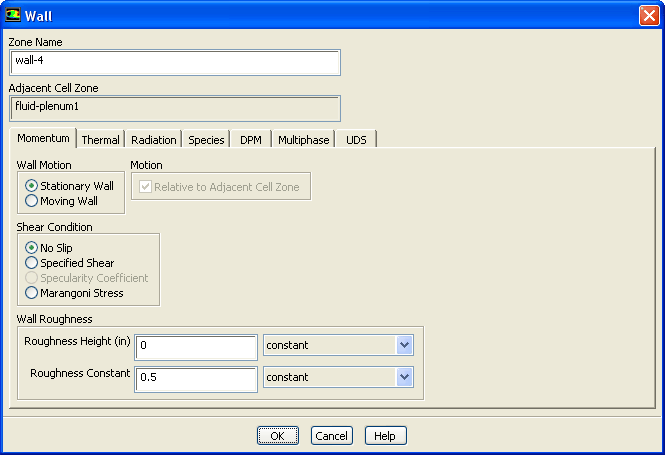
Retain the default boundary conditions for the plenum and hole walls (
wall-4 and
wall-5).
 Boundary Conditions

 wall-4
 Edit...
- 7.
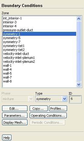
Verify that the symmetry planes are set to the correct type in the
Boundary Conditions task page.
 Boundary Conditions
- (a)
Select
symmetry-1 in the
Zone list.
- (b)
Make sure that
symmetry is selected from the
Type drop-down list.
- (c)
Similarly, verify that the zones
symmetry-5,
symmetry-7,
symmetry-tet1, and
symmetry-tet2 are set to the correct type.
- 8.
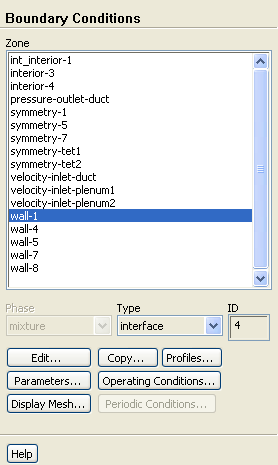
Define the zones on the non-conformal boundary as interface zones by changing the
Type for
wall-1,
wall-7, and
wall-8 to
interface.
-
The non-conformal mesh interface contains three boundary zones:
wall-1,
wall-7, and
wall-8.
wall-1 is the bottom surface of the duct,
wall-7 and
wall-8 represent the holes through which the cool air is injected from the plenum (Figure
7.4). These boundaries were defined as walls in the original mesh files (
film_hex.msh and
film_tet.msh) and must be redefined as
interface boundary types.
- (a)
Open the
Mesh Display dialog box.
 General
 Display...
- i.
Select
wall-1,
wall-7, and
wall-8 from the
Surfaces selection list.
-
Use the scroll bar to access the surfaces that are not initially visible in the
Mesh Display dialog box.
-
Note:
You may need to deselect all surfaces first by selecting the unshaded icon to the far right of
Surfaces.
- ii.
Click
Display and close the
Mesh Display dialog box.
- (b)
Display the bottom view.
 Graphics and Animations
 Views...
- i.
Select
bottom in the
Views list and click
Apply.
- ii.
Close the
Views dialog box.
-
Zoom in using the middle mouse button. Figure
7.4 shows the mesh for the
wall-1 and
wall-7 boundaries (i.e., hole-1). Similarly, you can zoom in to see the mesh for the
wall-1 and
wall-8 boundaries (i.e., hole-2).
Figure 7.4: Mesh for the
wall-1 and
wall-7 Boundaries
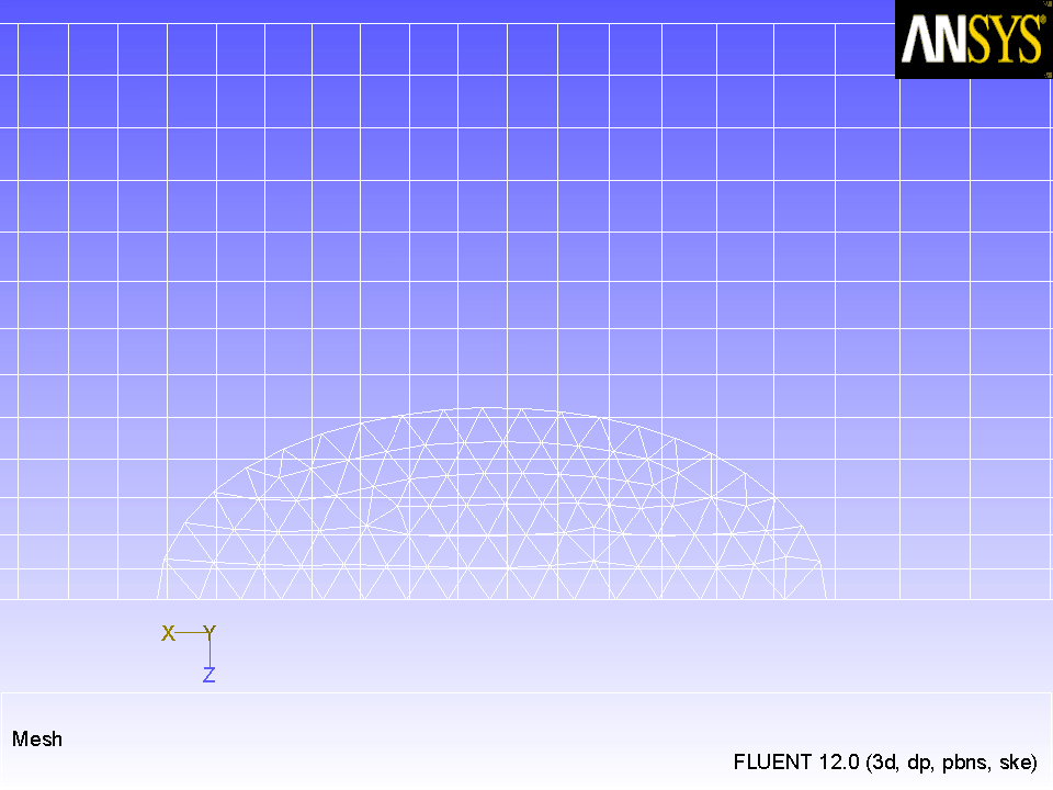 |
- (a)
Select
wall-1 in the
Zone list and select
interface as the new
Type.
 Boundary Conditions
-
A
Question dialog box will open, asking if it is
OK to change the type of
wall-1 from
wall to
interface. Click
Yes in the
Question dialog box.
-
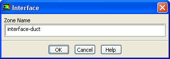
The
Interface dialog box will open and give the default name for the newly created interface zone.
- i.
Change the
Zone Name to
interface-duct.
- ii.
Click
OK to close the
Interface dialog box.
- (b)
Similarly, convert
wall-7 and
wall-8 to
interface boundary zones, specifying
interface-hole1 and
interface-hole2 for
Zone Name, respectively.
![[ANSYS, Inc. Logo]](fluentlogo.gif)


 Boundary Conditions