- 1.
Set the boundary conditions for the
baffle.
 Boundary Conditions

 baffle
 Edit...
- (a)
Click the
Thermal tab and enter
0.1 for
Internal Emissivity.
- (b)
Click the
Radiation tab and enter
0 for
Diffuse Fraction.
- (c)
Click
OK to close the
Wall dialog box.
- 2.
Set the boundary conditions for the
baffle-shadow.
 Boundary Conditions

 baffle-shadow
 Edit...
- (a)
Click the
Thermal tab and enter
0.1 for
Internal Emissivity.
- (b)
Click the
Radiation tab and enter
0 for
Diffuse Fraction.
- (c)
Click
OK to close the
Wall dialog box.
- 3.
Set the boundary conditions for the
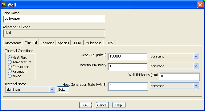
bulb-outer.
 Boundary Conditions

 bulb-outer
 Edit...
- (a)
Click the
Thermal tab and enter
150000
 for
Heat Flux.
for
Heat Flux.
- (b)
Retain the value of
1 for
Internal Emissivity.
- (c)
Click
OK to close the
Wall dialog box.
- 4.
Set the boundary conditions for the
housing.
 Boundary Conditions

 housing
 Edit...
- (a)
Click the
Thermal tab and select
Mixed in the
Thermal Conditions group box.
- (b)
Enter
10
 for
Heat Transfer Coefficient.
for
Heat Transfer Coefficient.
- (c)
Enter
20 C for
Free Stream Temperature.
- (d)
Retain the value of
1 for
External Emissivity.
- (e)
Enter
20 C for
External Radiation Temperature.
- (f)
Enter
0.5 for
Internal Emissivity.
- (g)
Click
OK to close the
Wall dialog box.
- 5.
Set the boundary conditions for the
lens-inner.
 Boundary Conditions

 lens-inner
 Edit...
-
The inner and outer surface of the lens will be set to semi-transparent conditions. This allows radiation to be transmitted through the wall between the two adjacent participating cell zones. It also calculates the effects of reflection and refraction at the interface. These effects occur because of the change in refractive index (set through the material properties) and are a function of the incident angle of the radiation and the surface finish. In this case, the lens is assumed to have a very smooth surface so the diffuse fraction will be set to 0.
On the internal walls (wall/ wall-shadows) it is important to note the adjacent cell zone: this is the zone the surface points into and may influence the settings on diffuse fraction (these can be different on both sides of the wall).
- (a)
Click the
Radiation tab.
- (b)
Select
semi-transparent from the
BC Type drop-down list.
- (c)
Enter
0 for
Diffuse Fraction.
- (d)
Click
OK to close the
Wall dialog box.
- 6.
Set the boundary conditions for the
lens-inner-shadow.
 Boundary Conditions

 lens-inner-shadow
 Edit...
- (a)
Click the
Radiation tab.
- (b)
Retain the default selection of
semi-transparent from the
BC Type drop-down list.
- (c)
Enter
0 for
Diffuse Fraction.
- (d)
Click
OK to close the
Wall dialog box.
- 7.
Set the boundary conditions for the
lens-outer.
 Boundary Conditions

 lens-outer
 Edit...
-
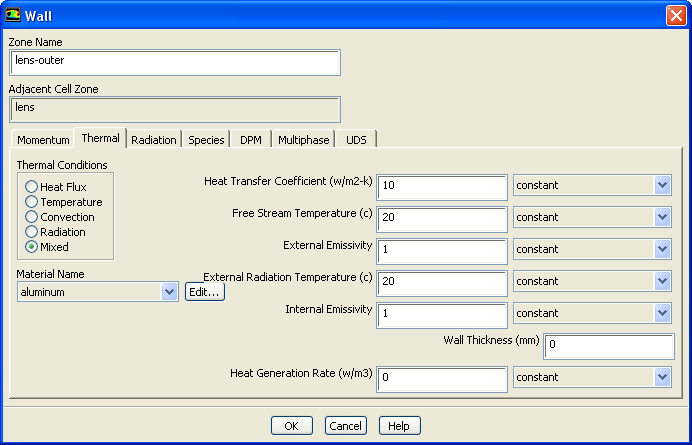
The surface of the lamp cools mainly by natural convection to the surroundings. As the outer lens is transparent it must also lose radiation to the surroundings, while the surroundings will supply a small source of background radiation associated with the temperature. For the lens, a semi-transparent condition is used on the outside wall. A mixed thermal condition provides the source of background radiation as well as calculating the convective cooling on the outer lens wall. For a semi-transparent wall, the source of background radiation is added directly to the DO radiation rather than to the energy equation - an external emissivity of 1 is used, in keeping with the assumption of a small object in a large enclosure. As the background radiation is supplied from the thermal conditions, there is no need to supply this as a source of irradiation under the
Radiation tab for the wall boundary condition. The only other setting required here is the surface finish of the outer surface of the lens - the diffuse fraction should be set to 0 as the lens is assumed to be smooth.
- (a)
Click the
Thermal tab and select
Mixed in the
Thermal Conditions group box.
- (b)
Enter
10
 for
Heat Transfer Coefficient.
for
Heat Transfer Coefficient.
- (c)
Enter
20 C for
Free Stream Temperature.
- (d)
Retain the value of
1 for
External Emissivity.
-
For a semi-transparent wall the internal emissivity has no effect as there is no absorption or emission on the surface. So the set value is irrelevant.
- (e)
Enter
20 C for
External Radiation Temperature.
- (f)
Click the
Radiation tab.
- (g)
Select
semi-transparent from the
BC Type drop-down list.
- (h)
Enter
0 for
Diffuse Fraction.
- (i)
Click
OK to close the
Wall dialog box.
- 8.
Set the boundary conditions for the
reflector.
 Boundary Conditions

 reflector
 Edit...
-
Like the baffles, the reflector is made of highly polished aluminum, giving it highly reflective surface property. About 90% of incident radiation reflects from this surface. Only 10% gets absorbed. Based on Kirchhoff's law, we can assume emissvity equals absorptivity. Therefore, we apply internal emissivity=0.1. We also assume a clean reflector (diffuse fraction = 0).
- (a)
Click the
Thermal tab and enter
0.1 for
Internal Emissivity.
- (b)
Click the
Radiation tab and enter
0 for
Diffuse Fraction.
- (c)
Click
OK to close the
Wall dialog box.
![[ANSYS, Inc. Logo]](fluentlogo.gif)


 Boundary Conditions