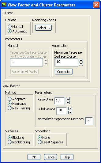
33.3.5 View Factor and Cluster Parameters Dialog Box
The
View Factor and Cluster Parameters dialog box allows you to set parameters related to surface clusters and view factors for the surface-to-surface radiation model. See Section
13.3.3 for information about using this dialog box.
Controls
Cluster
contains the methods and parameters for creating surface clusters.
Options
gives you a choice of forming clusters either manually or automatically.
Manual
allows you to form clusters manually.
Automatic
allows
ANSYS FLUENT to form the cluster automatically.
Radiating Zones
allows you to control the participation of s2s radiation. See Section
13.3.3 for more information.
Parameters
contains the parameters for creating surface clusters. See Section
13.3.3 for information about setting the parameters.
Manual
(available only when the
Manual option is enabled) allows you to manually specify the number of faces per surface cluster for the flow boundary zones.
Faces per Surface Cluster for Flow Boundary Zones
specifies the number of faces in each surface cluster for flow boundary zones. The default is set to
1. See
this section in the separate
Theory Guide for details about clustering.
Apply to All Walls
applies the value specified in the
Faces per Surface Cluster for Flow Boundary Zones field to all wall zones adjacent to fluid zones.
Automatic
(available only when the
Automatic option is enabled) allows you to automatically specify the maximum number of faces per surface cluster.
Maximum Faces per Surface Cluster
specifies the maximum number of faces in each surface cluster. The default is set to
10.
Compute
results in
ANSYS FLUENT automatically calculating and updating the face per surface cluster values in the boundary conditions dialog box without computing the clusters.
View Factor
contains parameters for computing the view factors.
Method
specifies the method for computing the view factors. See Section
13.3.3 for information about choosing a method.
Adaptive
specifies the use of the adaptive method for computing the view factors.
Hemicube
specifies the use of the hemicube method for computing the view factors. The hemicube method is available only for 3D and axisymmetric cases.
Ray Tracing
specifies the use of the ray tracing method for computing the view factors. The ray tracing method should not be used when any of the zones are defined as symmetric or periodic.
Surfaces
specifies the geometric orientation of surface pairs with respect to each other when using either the adaptive or hemicube method.
Blocking
specifies that there is another surface blocking the views between the surfaces under consideration.
Nonblocking
specifies that there is no obstruction between the surfaces under consideration.
Parameters
contains parameters related to the hemicube and ray tracing methods for computing the view factors. All of these inputs are available when
Hemicube is selected under
Method, whereas only
Resolution is available when
Ray Tracing is selected. See Section
13.3.3 for information about setting hemicube parameters.
Resolution
specifies the resolution of the hemicube. The default value is set to
10. You can increase the value to reduce aliasing effects that can lead to overestimated or underestimated view factors.
Subdivisions
specifies the number of subfaces into which each face is divided. The default value is set to
10. This parameter is only available for the hemicube method.
Normalized Separation Distance
specifies the ratio of the minimum face separation to the effective diameter of the face. The default value is set to
5. This parameter is only available for the hemicube method.
Smoothing
specifies whether or not smoothing should be performed on the view factor matrix when using the adaptive or hemicube method. See
this section in the separate
Theory Guide for details about smoothing.
None
specifies that the view factor matrix will not be smoothed.
Least Squares
specifies that the least-squares method will be used for smoothing the view factor matrix.
![[ANSYS, Inc. Logo]](fluentlogo.gif)