- 1.
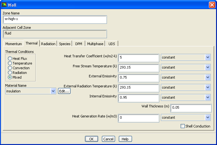
Set the boundary conditions for the front wall (
w-high-x).
 Boundary Conditions

 w-high-x
 Edit...
- (a)
Click the
Thermal tab and select
Mixed in the
Thermal Conditions group box.
- (b)
Select
insulation from the
Material Name drop-down list.
- (c)
Enter
5
 for
Heat Transfer Coefficient.
for
Heat Transfer Coefficient.
- (d)
Enter
293.15 K for both
Free Stream Temperature and
External Radiation Temperature.
- (e)
Enter
0.75 for
External Emissivity.
- (f)
Enter
0.95 for
Internal Emissivity.
- (g)
Enter
0.05 m for
Wall Thickness.
- (h)
Click
OK to close the
Wall dialog box.
- 2.
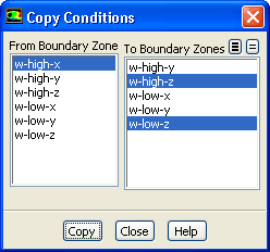
Copy boundary conditions to define the side walls
w-high-z and
w-low-z.
 Boundary Conditions
 Copy...
- (a)
Select
w-high-x from the
From Boundary Zone selection list.
- (b)
Select
w-high-z and
w-low-z from the
To Boundary Zones selection list.
- (c)
Click
Copy.
-
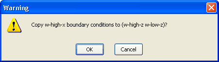
A
Warning dialog box will open, asking if you want to copy the boundary conditions of
w-high-x to
w-high-z and
w-low-z.
- (d)
Click
OK in the
Warning dialog box.
- (e)
Close the
Copy Conditions dialog box.
- 3.
Set the boundary conditions for the heated wall (
w-low-x).
 Boundary Conditions

 w-low-x
 Edit...
- (a)
Click the
Thermal tab and select
Temperature in the
Thermal Conditions group box.
- (b)
Retain the default selection of
aluminum from the
Material Name drop-down list.
- (c)
Enter
473.15 K for
Temperature.
- (d)
Enter
0.95 for
Internal Emissivity.
- (e)
Click
OK to close the
Wall dialog box.
- 4.
Set the boundary conditions for the top wall (
w-high-y).
 Boundary Conditions

 w-high-y
 Edit...
- (a)
Click the
Thermal tab and select
Mixed in the
Thermal Conditions group box.
- (b)
Select
insulation from the
Material Name drop-down list.
- (c)
Enter
3
 for
Heat Transfer Coefficient.
for
Heat Transfer Coefficient.
- (d)
Enter
293.15 K for both
Free Stream Temperature and
External Radiation Temperature.
- (e)
Enter
0.75 for
External Emissivity.
- (f)
Enter
0.95 for
Internal Emissivity.
- (g)
Enter
0.05 m for
Wall Thickness.
- (h)
Click
OK to close the
Wall dialog box.
- 5.
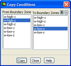
Copy boundary conditions to define the bottom wall (
w-low-y).
 Boundary Conditions
 Copy...
- (a)
Select
w-high-y from the
From Boundary Zone selection list.
- (b)
Select
w-low-y from the
To Boundary Zones selection list.
- (c)
Click
Copy.
-
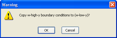
A
Warning dialog box will open, asking if you want to copy the boundary conditions of
w-high-y to
w-low-y.
- (d)
Click
OK in the
Warning dialog box.
- (e)
Close the
Copy Conditions dialog box.
![[ANSYS, Inc. Logo]](fluentlogo.gif)


 Boundary Conditions