[ANSYS, Inc. Logo] return to home search
next up previous contents

Step 3: Models

figure Models

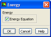
1.   Enable the energy equation.

figure Models figure figure Energy figure Edit...

figure

2.   Enable the Surface to Surface (S2S) radiation model.

figure Models figure figure Radiation figure Edit...

figure

(a)   Select Surface to Surface (S2S) in the Model list.

  The Radiation Model dialog box will expand to show additional inputs for the S2S model.

  The surface-to-surface (S2S) radiation model can be used to account for the radiation exchange in an enclosure of gray-diffuse surfaces. The energy exchange between two surfaces depends in part on their size, separation distance, and orientation. These parameters are accounted for by a geometric function called a "view factor".

The S2S model assumes that all surfaces are gray and diffuse. Thus according to the gray-body model, if a certain amount of radiation is incident on a surface, then a fraction is reflected, a fraction is absorbed, and a fraction is transmitted. The main assumption of the S2S model is that any absorption, emission, or scattering of radiation by the medium can be ignored. Therefore only "surface-to-surface" radiation is considered for analysis.

For most applications the surfaces in question are opaque to thermal radiation (in the infrared spectrum), so the surfaces can be considered opaque. For gray, diffuse, and opaque surfaces it is valid to assume that the emissivity is equal to the absorptivity and that reflectivity is equal to 1 minus the emissivity.

When the S2S model is used, you also have the option to define a "partial enclosure" which allows you to disable the view factor calculation for walls with negligible emission/absorption or walls that have uniform temperature. The main advantage of this option is to speed up the view factor calculation and the radiosity calculation.

(b)   Click the Set... button in the Parameters group box to open the View Factor and Cluster Parameters dialog box.

  You will define the view factor and cluster parameters.

figure

i.   Retain the value of 1 for Faces per Surface Cluster for Flow Boundary Zones in the Parameters group box.

ii.   Click Apply to All Walls.

  The S2S radiation model is computationally very expensive when there are a large number of radiating surfaces. The number of radiating surfaces is reduced by clustering surfaces into surface "clusters''. The surface clusters are made by starting from a face and adding its neighbors and their neighbors until a specified number of faces per surface cluster is collected.

For a small 2D problem, the default value of 1 for Faces per Surface Cluster for Flow Boundary Zones is acceptable. For a large problem you can increase this number to reduce the memory requirement for the view factor file that is saved in a later step. This may also lead to some reduction in the computational expense. However, this is at the cost of some accuracy. This tutorial illustrates the influence of clusters.

iii.   Select Ray Tracing in the Method list in the View Factor group box.

iv.   Click OK to close the View Factor and Cluster Parameters dialog box.

(c)   Click Compute/Write... for Methods in the View Factors group box to open the Select File dialog box and to compute the view factors.

  The file created in this step will store the cluster and view factor parameters.

  You need to perform this step if the problem is being solved for the first time. For subsequent calculations you can read the view factor and cluster information from an existing file (by clicking Read... instead of Compute/Write...).

i.   Enter rad_1.s2s.gz as the file name for S2S File.

ii.   Click OK in the Select File dialog box.

Note:   The size of the view factor file can be very large if not compressed. It is highly recommended to compress the view factor file by providing .gz or .Z extension after the name (i.e. rad_1.gz or rad_1.Z). For small files, you can provide the .s2s extension after the name.

   ANSYS FLUENT will print an informational message describing the progress of the view factor calculation in the console.

(d)   Click OK to close the Radiation Model dialog box.


next up previous contents Previous: Step 2: General Settings
Up: Modeling Radiation and Natural
Next: Step 4: Materials
Release 12.0 © ANSYS, Inc. 2009-02-09