1.
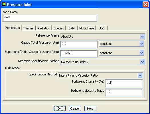
Set the boundary conditions for the nozzle inlet (
inlet).
Boundary ConditionsinletEdit...
(a)
Enter
0.9 atm for
Gauge Total Pressure.
(b)
Enter
0.7369 atm for
Supersonic/Initial Gauge Pressure.
The inlet static pressure estimate is the mean pressure at the nozzle exit. This value will be used during the solution initialization phase to provide a guess for the nozzle velocity.
(c)
Select
Intensity and Viscosity Ratio from the
Specification Method drop-down list in the
Turbulence group box.
(d)
Enter
1.5% for
Turbulent Intensity.
(e)
Enter
10 for
Turbulent Viscosity Ratio.
(f)
Click
OK to close the
Pressure Inlet dialog box.
2.
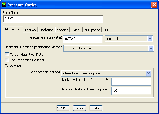
Set the boundary conditions for the nozzle exit (
outlet).
Boundary ConditionsoutletEdit...
(a)
Enter
0.7369 atm for
Gauge Pressure.
(b)
Select
Intensity and Viscosity Ratio from the
Specification Method drop-down list in the
Turbulence group box.
(c)
Enter
1.5% for
Backflow Turbulent Intensity.
(d)
Enter
10 for
Backflow Turbulent Viscosity Ratio.
If substantial backflow occurs at the outlet, you may need to adjust the backflow values to levels close to the actual exit conditions.
(e)
Click
OK to close the
Pressure Outlet dialog box.
![[ANSYS, Inc. Logo]](fluentlogo.gif)


 Boundary Conditions
 Boundary Conditions

 inlet
inlet
 Edit...
 Boundary Conditions

 outlet
 Edit...