Step 7: Boundary Conditions
Boundary Conditions
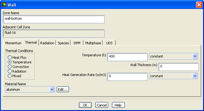
1. Set the boundary conditions for the bottom wall of the left tube (
wall-21
).
Boundary Conditions
wall-21
Edit...
(a) Enter
wall-bottom
for
Zone Name
.
(b) Click the
Thermal
tab.
i. Select
Temperature
in the
Thermal Conditions
list.
ii. Enter
400
K for
Temperature
.
These settings will specify a constant wall temperature of 400 K.
(c) Click
OK
to close the
Wall
dialog box.
2. Set the boundary conditions for the top wall of the right tube (
wall-3
).
Boundary Conditions
wall-3
Edit...
(a) Enter
wall-top
for
Zone Name
.
(b) Click the
Thermal
tab.
i. Select
Temperature
from the
Thermal Conditions
list.
ii. Enter
400
K for
Temperature
.
(c) Click
OK
to close the
Wall
dialog box.
Previous:
Step 6: Periodic Conditions
Up:
Modeling Periodic Flow and
Next:
Step 8: Solution
Release 12.0 ©
ANSYS, Inc.
2009-02-09
![[ANSYS, Inc. Logo]](fluentlogo.gif)


 Boundary Conditions
 Boundary Conditions

 wall-21
 Edit...
 Boundary Conditions

 wall-3
 Edit...
Previous:
Step 6: Periodic Conditions
Edit...
Previous:
Step 6: Periodic Conditions