![[ANSYS, Inc. Logo]](fluentlogo.gif)


|
|
|
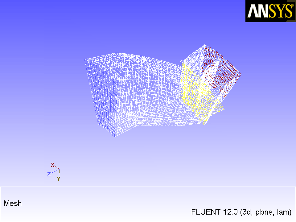
 General
 General
 Check
Check
 Enter
Enter
 in the console to get the command prompt (
 ).
).
> mesh

/mesh> modify-zones

/mesh/modify-zones> list-zones

  id  name                       type                material              kind
----  -------------------------  ------------------  --------------------  ----
  13  fluid-rotor                fluid               air                   cell
  28  fluid-stator               fluid               air                   cell
   2  default-interior:0         interior                                  face
  15  default-interior           interior                                  face
   3  rotor-hub                  wall                aluminum              face
   4  rotor-shroud               wall                aluminum              face
   7  rotor-blade-1              wall                aluminum              face
   8  rotor-blade-2              wall                aluminum              face
  16  stator-hub                 wall                aluminum              face
  17  stator-shroud              wall                aluminum              face
  20  stator-blade-1             wall                aluminum              face
  21  stator-blade-2             wall                aluminum              face
  22  stator-blade-3             wall                aluminum              face
  23  stator-blade-4             wall                aluminum              face
   5  rotor-inlet                pressure-inlet                            face
  19  stator-outlet              pressure-outlet                           face
  10  rotor-per-1                wall                aluminum              face
  12  rotor-per-2                wall                aluminum              face
  24  stator-per-2               wall                aluminum              face
  26  stator-per-1               wall                aluminum              face
   6  rotor-interface            interface                                 face
  18  stator-interface           interface                                 face
  11  rotor-per-4                wall                aluminum              face
   9  rotor-per-3                wall                aluminum              face
  25  stator-per-4               wall                aluminum              face
  27  stator-per-3               wall                aluminum              face

/mesh/modify-zones> make-periodic

Periodic zone [()] 10

Shadow zone [()] 9

Rotational periodic? (if no, translational) [yes] yes

Create periodic zones? [yes] yes


  all 176 faces matched for zones 10 and 9.
    zone 9 deleted
     created periodic zones.
|
| Zone Pairs | Respective Zone IDs |
|---|---|
| rotor-per-2 and rotor-per-4 | 12 and 11 |
| stator-per-1 and stator-per-3 | 26 and 27 |
| stator-per-2 and stator-per-4 | 24 and 25 |
 General
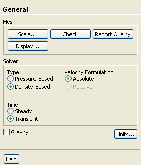
 General
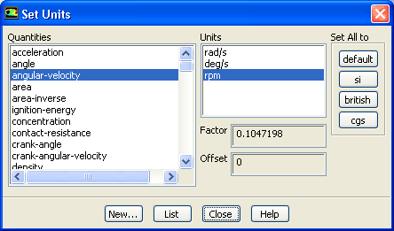
 Units...
Previous:
Step 1: Mesh