![[ANSYS, Inc. Logo]](fluentlogo.gif)


|
|
|
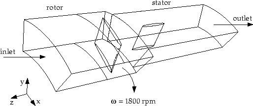
The problem to be considered is shown schematically in Figure 11.1. The rotor and stator consist of 9 and 12 blades, respectively. A steady-state solution for this configuration using only one rotor blade and one stator blade is desired. Since the periodic angles for the rotor and stator are different, a mixing plane must be used at the interface.
The mixing plane is defined at the rotor outlet/stator inlet. The mesh is set up with periodic boundaries on either side of the rotor and stator blades. A pressure inlet is used at the upstream boundary and a pressure outlet at the downstream boundary. Ambient air is drawn into the fan (at 0 Pa gauge total pressure) and is exhausted back out to the ambient environment (0 Pa static pressure). The hub and blade of the rotor are assumed to be rotating at 1800 rpm.
Previous:
Prerequisites