ANSYS FLUENT will perform various checks on the mesh and report the progress in the console. Make sure that the reported minimum volume is a positive number.
Extra:
You can use the right mouse button to check which zone number corresponds to each boundary. If you click the right mouse button on one of the boundaries in the graphics window, information will be displayed in the
ANSYS FLUENT console about the associated zone, including the name of the zone. This feature is especially useful when you have several zones of the same type and you want to distinguish between them quickly.
3.
Define new units
for angular velocity and length.
GeneralUnits...
In the problem description, angular velocity and length are specified in rpm and cm, respectively, which is more convenient in this case. These are not the default units for these quantities.
(a)
Select
angular-velocity from the
Quantities list, and
rpm in the
Units list.
(b)
Select
length from the
Quantities list, and
cm in the
Units list.
(c)
Close the
Set Units dialog box.
4.
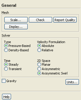
Specify the solver formulation to be used for the model calculation and enable the modeling of axisymmetric swirl.
General
(a)
Retain the default selection of
Pressure-Based in the
Type list.
(b)
Retain the default selection of
Absolute in the
Velocity Formulation list.
For a rotating reference frame, the absolute velocity formulation has some numerical advantages.
(c)
Select
Axisymmetric Swirl in the
2D Space list.
![[ANSYS, Inc. Logo]](fluentlogo.gif)


 General
 General
 Check
Check
 General
 Units...

 General