Step 6: Boundary Conditions
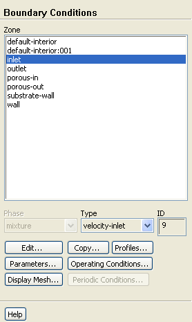
Boundary Conditions
1. Set the velocity and turbulence boundary conditions at the inlet (
inlet
).
Boundary Conditions
inlet
Edit...
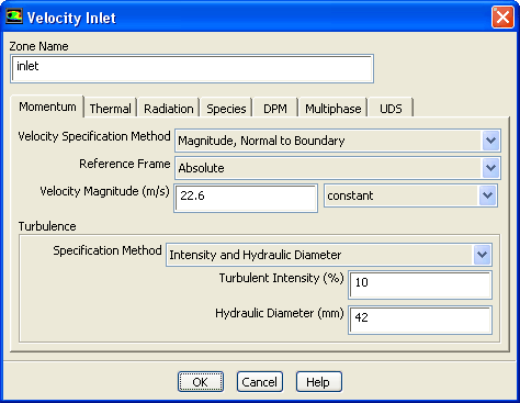
(a) Enter
22.6
m/s for
Velocity Magnitude
.
(b) Select
Intensity and Hydraulic Diameter
from the
Specification Method
drop-down list in the
Turbulence
group box.
(c) Retain the default value of
10
% for the
Turbulent Intensity
.
(d) Enter
42
mm for the
Hydraulic Diameter
.
(e) Click
OK
to close the
Velocity Inlet
dialog box.
2. Set the boundary conditions at the outlet (
outlet
).
Boundary Conditions
outlet
Edit...
(a) Retain the default setting of
0
for
Gauge Pressure
.
(b) Select
Intensity and Hydraulic Diameter
from the
Specification Method
drop-down list in the
Turbulence
group box.
(c) Enter
5
% for the
Backflow Turbulent Intensity
.
(d) Enter
42
mm for the
Backflow Hydraulic Diameter
.
(e) Click
OK
to close the
Pressure Outlet
dialog box.
3. Retain the default boundary conditions for the walls (
substrate-wall
and
wall
).
Previous:
Step 5: Cell Zone
Up:
Modeling Flow Through Porous
Next:
Step 7: Solution
Release 12.0 ©
ANSYS, Inc.
2009-02-09
![[ANSYS, Inc. Logo]](fluentlogo.gif)


 Boundary Conditions
 Boundary Conditions

 inlet
inlet
 Edit...
 Boundary Conditions

 outlet
 Edit...
 Previous:
Step 5: Cell Zone
Previous:
Step 5: Cell Zone