The
Append Case File... functionality allows you to combine two mesh files into one single mesh file.
3.
Check the mesh.
GeneralCheck
ANSYS FLUENT will perform various checks on the mesh and report the progress in the console. Make sure that the reported minimum volume is a positive number.
4.
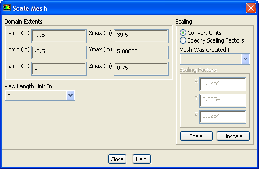
Scale the mesh and change the unit of length to inches.
GeneralScale...
(a)
Make sure that
Convert Units is selected in the
Scaling group box.
(b)
Select
in from the
Mesh Was Created In drop-down list by first clicking the down-arrow button and then clicking the
in item from the list that appears.
(c)
Click
Scale to scale the mesh.
Domain Extents will continue to be reported in the default SI unit of meters.
(d)
Select
in from the
View Length Unit In drop-down list to set inches as the working unit for length.
(e)
Close the
Scale Mesh dialog box.
5.
Check the mesh.
GeneralCheck
Note:
It is a good idea to check the mesh after you manipulate it (i.e., scale, convert to polyhedra, merge, separate, fuse, add zones, or smooth and swap.) This will ensure that the quality of the mesh has not been compromised.
6.
Display an outline of the 3D mesh.
GeneralDisplay...
(a)
Retain the default selections in the
Surfaces list.
(b)
Click
Display.
(c)
Close the
Mesh Display dialog box.
7.
Manipulate the mesh display to obtain a front view as shown in Figure
7.2.
Graphics and AnimationsViews...
(a)
Select
front in the
Views list.
(b)
Click
Apply.
(c)
Close the
Views dialog box.
Figure 7.2: Hybrid Mesh for Film Cooling Problem
8.
Zoom in using the middle mouse button to view the hole and plenum regions (Figure
7.3).
Figure 7.3: Hybrid Mesh (Zoomed-In View)
In Figure
7.3, you can see the quadrilateral faces of the hexahedral cells that are used to model the duct region and the triangular faces of the tetrahedral cells that are used to model the plenum and hole regions, resulting in a hybrid mesh.
Extra:
You can use the right mouse button to check which zone number corresponds to each boundary. If you click the right mouse button on one of the boundaries in the graphics window, its zone number, name, and type will be printed in the
ANSYS FLUENT console. This feature is especially useful when you have several zones of the same type and you want to distinguish between them quickly.