[ANSYS, Inc. Logo] return to home search
next up previous contents

Step 3: Prepare the Case and Set the Viewer Options

1.   If you have launched CFD-Post from ANSYS FLUENT, proceed to the next step. For all other situations, load the simulation from the data file ( elbow1.cdat.gz) from the menu bar by selecting File/Load Results. In the Load Results File dialog box, select elbow1.cdat.gz and click Open.

2.   If you see a pop-up that discusses Global Variables Ranges, it can be ignored. Click OK.

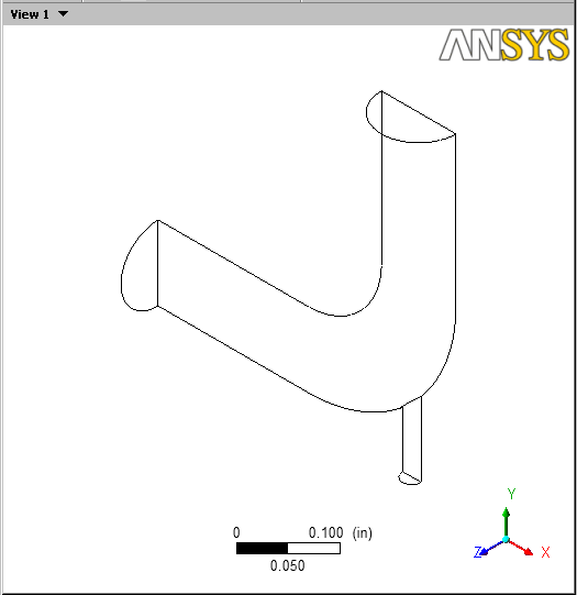
The mixing elbow appears in the 3D Viewer in an isometric orientation. The wireframe appears in the view and there is a check mark beside User Location and Plots / Wireframe in the Outline tree view; the check mark indicates that the wireframe is visible in the 3D Viewer.

3.   Optionally, set the viewer background to white:
(a)   Right-click on the viewer and select Viewer Options.

(b)   In the Options dialog box, select CFD-Post / Viewer.

(c)   Set:
  • Background / Color Type to Solid.

  • Background / Color to white. To do this, click the bar beside the Color label to cycle through 10 basic colors. (Click the right-mouse button to cycle backwards.) Alternatively, you can choose any color by clicking figure to the right of the Color option.

  • Text Color to black (as above).

  • Edge Color to black (as above).

(d)   Click OK to have the settings take effect.

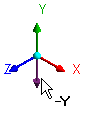
(e)   Experiment with rotating the object by clicking on the arrows of the triad in the 3D Viewer. This is the triad:

figure

In the picture of the triad above, the cursor is hovering in the area opposite the positive Y axis, which reveals the negative Y axis.
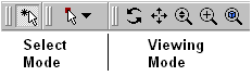
Note:    The viewer must be in "viewing mode'' for you to be able to click on the triad. You set viewing mode or select mode by clicking the icons in the viewer toolbar:

figure

When you have finished experimenting, click the cyan (ISO) sphere in the triad to return to the isometric view of the object.
4.   Set CFD-Post to display objects in the units you want to see. These display units are not necessarily the same types as the units in the results files you load; however, for this tutorial you will set the display units to be the same as the solution units for consistency. As mentioned in the Problem Description, the solution units are SI, except for the length, which is measured in inches.

(a)   Right-click on the viewer and select Viewer Options.

  The Options dialog box is where you set your preferences.

(b)   In the Options dialog box, select Common / Units.

(c)   Notice that System is set to SI. In order to be able to change an individual setting (length, in this case) from SI to imperial, set System to Custom. Now set Length to in (inches) and click OK.

Note:   
  • The display units you set are saved between sessions and projects. This means that you can load results files from diverse sources and always see familiar units displayed.

  • You have set only length to inches; volume will still be reported in meters. To change volume as well, in the Options dialog box, select Common / Units, then click More Units to find the full list of settings.

figure


next up previous contents Previous: Step 2: Display the
Up: Introduction to Using CFD-Post:
Next: Step 4: View and
Release 12.0 © ANSYS, Inc. 2009-03-30