Optionally, take a few moments to become familiar with the viewer controls. These icons switch the mouse from selecting items in the viewer to controlling the orientation and display of the view. First, the sizing controls:
- 1.
Click the
Zoom Box icon
 .
.
- 2.
Click and drag a rectangular box over the geometry.
- 3.
Release the mouse button to zoom in on the selection.
The geometry zoom changes to display the selection at a greater resolution.
- 4.
Click the
Fit View icon
 to re-center and re-scale the geometry.
Now, the rotation functions:
- 1.
Click the
Rotate icon
 on the viewer toolbar.
- 2.
Click and drag repeatedly within the viewer to test the rotation of the geometry. Notice how the mouse cursor changes depending on where you are in the viewer, particularly near the edges:
Figure 1.3: Orientation Control Cursor Types
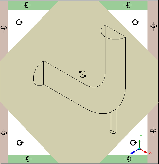 |
The geometry rotates based on the direction of movement. If the mouse cursor has an axis (which happens around the edges), the object rotates around the axis shown in the cursor. The axis of rotation is through the pivot point, which defaults to be in the center of the object.
Now explore orientation options:
- 1.
Right-click a blank area in the viewer and select
Predefined Camera / View Towards -X.
- 2.
Right-click a blank area in the viewer and select
Predefined Camera / Isometric View (Z Up).
- 3.
Click the "Z'' axis of triad in the viewer to get a side view of the object.
- 4.
Click the three axes in the triad in turn to see the vector objects in all three planes; when you are done, click the cyan (ISO) sphere.
Now explore the differences between the orienting controls you just used and
select mode.
- 1.
Click the
 icon to enter select mode.
- 2.
Hover over one of the wireframe lines and notice that the cursor turns into a box.
- 3.
Click a wireframe line and notice that the
Details view for the wireframe appears.
- 4.
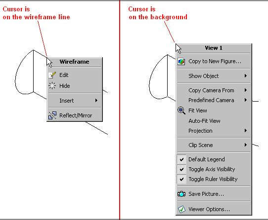
Right-click away from a wireframe line and then again on a wireframe line. Notice how the menu changes:
Figure 1.4: Right-click Menus Vary by Cursor Position
 |
- 5.
In the
Outline tree view, select the
elbow1 / fluid / wall check box; the outer wall of the elbow becomes solid. Notice that as you hover over the colored area, the cursor again becomes a box, indicating that you can perform operations on that region. When you right-click on the wall, a new menu appears.
- 6.
Click on the triad and notice that you cannot change the orientation of the viewer object. (The triad is available only in viewing mode, not select mode.)
- 7.
In the
Outline tree view, clear the
elbow1 / fluid / wall check box; the outer wall of the elbow disappears.


 Previous:
Step 5: View Simulation
Previous:
Step 5: View Simulation
Up:
Introduction to Using CFD-Post:
Next:
Step 7: Create an
Release 12.0 © ANSYS, Inc. 2009-03-30 ![[ANSYS, Inc. Logo]](fluentlogo.gif)

